


Interrupts
Interrupt Setup Examples
MN102H75K/F75K/85K/F85K LSI User Manual Panasonic Semiconductor Development Company
41
Panasonic
3. Enable interrupts by writing a 1 to the interrupt enable flag (IE) in the PSW
and setting the interrupt masking level (IM[2:0]) to 7 (b’111’).
Now if a falling edge occurs on IRQ0 (P00), an interrupt will occur. If the
CPU accepts the interrupt, the program branches to address x’080008’.
■
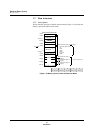
Servicing the interrupt
The main program normally gen-
erates and branches to the inter-
rupt start address.
4. During interrupt preprocessing, read the accepted interrupt group number
register (IAGR) to determine the interrupt group (group 4, in this case).
5. Branch to the interrupt service routine.
During the interrupt service rou-
tine, prevent the CPU from
accepting any other maskable
interrupts by setting the IM[2:0]
and IE bits of the PSW to 0.
6. At the beginning of the interrupt service routine, clear the IQ0IR bit in
IQ0ICL to 0.
To accept the same interrupt
during the interrupt service rou-
tine, clear IR flag at the begin-
ning of it.
7. After the service routine ends, return to the main program with the RTI
instruction.
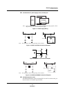
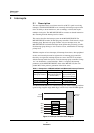
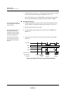
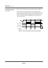
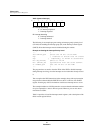
Figure 2-5 Timing for External Pin Interrupt Setup (Example)
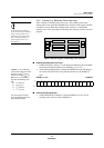
EXTMD(W) IQ0ICL(B)
Low level
Falling edge
(1) (2)(3) (4)(5)(6)(7)
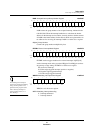
IQ0ICL(B)IQ0ICH(B)
(4)(5)(6)(7)
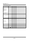
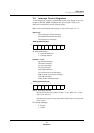
Registers [R/W]
Sequence
P00 (IRQ0)
EXTMD
IQ0IE
IQ0IR
Interrupt servicing
IQ0ICL(B)