


Closed-Caption Decoder
Functional Description
Panasonic Semiconductor Development Company MN102H75K/F75K/85K/F85K LSI User Manual
230
Panasonic
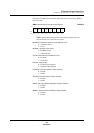
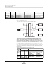
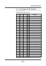
Table 9-5 provides the registers used to control and monitor the clamping circuit.
See the page number indicated for register and bit descriptions.
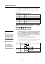
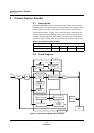
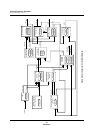
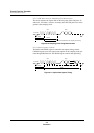
9.3.3 Sync Separator Circuit
A low-pass filter and a sync separator comprise this block. The sync separator
extracts HSYNC and VSYNC from the composite video signal. Figure 9-6 shows
a block diagram of the circuit, and table 9-6 provides the registers used to control
and monitor it. See the page number indicated for register and bit descriptions.
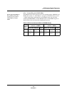
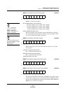
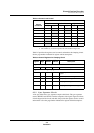
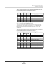
Table 9-4 Current Level Control
Control
Conditions
Current Source
Low Current Medium Current High Current
(1) (2) (3) (4) (5) (6)
10 ≤ A Off On Off On Off On
4 ≤ A ≤ 9 Off
On Off On Off Off
1 ≤ A ≤ 3 Off
On Off Off Off Off
A= 0 Off Off Off Off Off Off
-3 ≤ A ≤ -1
On Off Off Off Off Off
-9 ≤ A ≤ -4
On Off On Off Off Off
A ≤ -10
On Off On Off On Off
Notes: 1. A = compare level - reference level
2. The numbers (1) to (6) correspond to the same number in figure 9-5.
Table 9-5 Control Registers for Clamping Circuit
Register Page
CCDO
Address
CCD1
Address Description
Register for selecting the low-pass filter
NFSEL 242 x’007EC0’ x’007EE0’ Noise filter select register
Registers for controlling clamping
SCMING 243 x’007EC4’ x’007EE4’ Minimum sync level detection interval set
register
SYNCMIN 244 x’007EC8’ x’007EE8’ Sync and pedestal level register
BPPST 243 x’007EC6’ x’007EE6’ Backporch position register
CLAMP 245 x’007ECC’ x’007EEC
’
Clamping control register
CLPCND
1
248 x’007EDC’ x’007EEC
’
Clamping control signal status register 1