


Serial Interfaces
Serial Interface Setup Examples
MN102H75K/F75K/85K/F85K LSI User Manual Panasonic Semiconductor Development Company
137
Panasonic
5.6.4 Setting Up I
2
C Transmission Using Serial Interface 0
This example illustrates the microcontroller as a master transmitter in the I
2
C
mode, using the SBO0 and SBT0 pins.
■
To set up the output ports:
I
2
C mode requires open-drain
pins. To set this up, set the
ODASCI0 bit of PCNT0
(x’00FF90’) to 1. In addition, set
the P5PUP7 and P5PUP5 bits of
P5PUP (x’00FFB5’) to enable
pullup control of the SBO0 and
STB0.
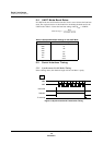
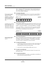
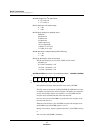
Set the P5MD7 and P5MD5 bits of the port 5 output mode register (P5MD) to 1.
This selects the SBO0 and SBT0 pins as the output port for the I
2
C interface.
P5MD (example) x’00FFFA’
■ To set up the I
2
C interface:
The parity bits serve as the ACK
signal. To output an ACK = 1 sig-
nal, select a fixed parity of 1. To
output an ACK = 0 signal, select
a fixed parity of 0. Select a parity
of none if there is no ACK signal.
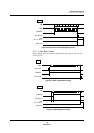
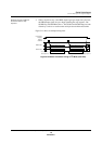
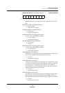
Set the operating conditions in the serial control register (SC0CTR). Select ACK
= 1 output for the transfer clock (SC0PTY[2:0] = b’101’), 8-bit character length
(SCLN = 1), I
2
C protocol (SC0PTL = 1), I
2
C mode (SC0ICM = 1), and MSB-
first bit order (SC0OD = 1). Enable both transmission and reception (SC0TEN
and SC0REN = 1) and disable transmission breaks (SC0BRE = 0). Select the
timer 0 underflow rate divided by 8 as the clock source.
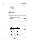
SC0CTR (example) x’00FD80’
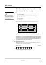
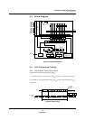
■ To set up the start sequence:
Reception must be enabled for
the circuit to detect a start
sequence.
Write a 1 to the SC0IIC bit of the SC0CTR register to signal the start sequence.
The SBO0 pin output immediately goes low. Read SC0STR to verify that the
start sequence occurred correctly (SC0IST = 1). At this point, even if another
start exists on the bus, an arbitration lost will not be detected.
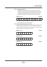
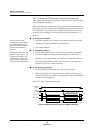
■
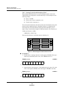
To transmit the first data byte:
1. Load the data to the serial port 0 transmit/receive buffer, which initiates data
output. The SBO0 pin begins data output to the I
2
C bus when the SBT0
clock signal goes low, with a 1/8 clock cycle delay.
2. After transmission, both the SBO0 and SBT0 signals stay low.
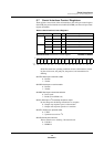
■
To transmit a second data byte:
Load the data to the serial port 0 transmit/receive buffer. The sequence for the
first data byte repeats.
■
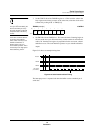
To set up the stop sequence:
1. When all the data has been transmitted, set the SC0IIC bit of SC0CTR to 0.
Never perform this step during transmission.
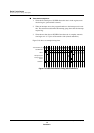
Bit:76543210
P5
MD7
P5
MD6
P5
MD5
P5
MD4
P5
MD3
P5
MD2
P5
MD1
P5
MD0
Setting:10100000
Bit:1514131211109876543210
SC0
TEN
SC0
REN
SC0
BRE
SC0
I2CS
SC0
PTL
—
SC0
OD
SC0
I2CM
SC0
LN
SC0
PTY2
SC0
PTY1
SC0
PTY0
SC0
SB
—
SC0
S1
SC0
S0
Setting:1100101111010001