


Closed-Caption Decoder
Functional Description
MN102H75K/F75K/85K/F85K LSI User Manual Panasonic Semiconductor Development Company
233
Panasonic
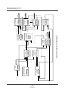
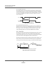
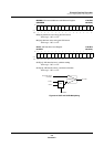
9.3.3.2 VSYNC Separator
The VSYNC separator extracts the VSYNC signal from the composite signal.
Like the HSYNC separator, it contains programmable methods for eliminating
noise. The VCNT register contains these settings. Masking the 0H to 127H range
(by setting the VSEPSEL bit of VCNT to 0) prevents VSYNC errors due to
noise. See figure 9-8.
9.3.3.3 Field Detection Circuit
The field detection circuit detects the phase difference between VSYNC and
HSYNC, based on the setting in the VPHASE[9:0] field of the FIELD register.
This setting is in units of the sampling clock for the HSYNC separator. The
results of the field detection are stored in the ODDEVEN bit of FIELD.
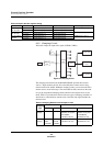
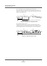
9.3.4 Data Slicer
The data slicer contains the maximum and minimum detection circuits, the slice
level calculator, and the slicer. The circuit compares the 8-bit digital values
output from the ADC to the slice level, which can be calculated by the hardware
or set in the software. It then outputs the results in serial 0s and 1s.
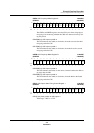
The data slicer calculates the slice level (the level above which a signal is 1 and
below which is 0) from the maximum and minimum clock run-in (CRI) pulses
occurring in the interval between the settings in the CRI1S and CRI1E registers.
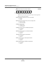
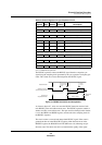
Figure 9-8 VSYNC Masking
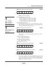
Figure 9-9 Data Slice Level Calculation
VSYNC
Masked
signal
127H
HSYNC
CRI Data
CRI1S
CRI1E
(max + min)/2 of this interval = slice level (computed in the hardware)