


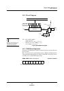

Pulse Width Modulator
Description
MN102H75K/F75K/85K/F85K LSI User Manual Panasonic Semiconductor Development Company
249
Panasonic
10 Pulse Width Modulator
10.1 Description
For information on the SLOW
mode, see section 3.1, “CPU
Modes.”
The MN102H75K/85K contains seven 8-bit pulse width modulators (PWMs)
with a minimum pulse width of 16/f
SYSCLK
and an output waveform cycle of
2
12
/f
SYSCLK
. (With a 4-MHz oscillator, 16/f
SYSCLK
= 1.33 µs (8 µs for SLOW
mode) and 2
12
/f
SYSCLK
= 341.3 µs (2 ms for SLOW mode).)
The PWM ports are 3.3-volt, open-drain outputs. To enable the PWM ports,
either turn the pullup registers on using the pullup control registers for the asso-
ciated ports (P15-P17 and P20-P23; see table 10-1) or connect external pullup
resistors to these ports.
The microcontroller writes the pulsewidth modulated data for a PWM block to its
associated 8-bit data register (PWMn). The data register settings determine how
long the waveform stays low. With a 4-MHz oscillator, the PWM output pulse
width has a resolution of 1.33 µs (1/f
PWM
) and a cycle of 341.3 µs (2
8
/f
PWM
).
Note that when (and only when) the data changes between x’00’ and x’01’, the
resolution is 1.34 µs (2/f
PWM
).
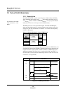
Table 10-1 Register Settings for Internal PWM Pullup
PWM Block Register Bit No. Setting
PWM0
P1PUP
(x’00FFB1’)
5
1PWM1 6
PWM2 7
PWM3
P2PUP
(x’00FFB2’)
0
1
PWM4 1
PWM5 2
PWM6 3
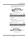
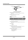
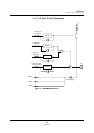
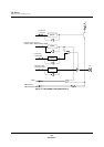
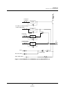
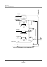
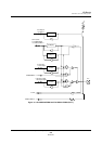
Figure 10-1 PWM Output Waveform
Output WavePWM Data
00
01
.
.
.
.
.
.
.
.
FE
FF
341.3 µs (2 ms for SLOW mode)
t
LOW
1.33 µs (8 µs for SLOW mode)
High level
Low level