


I
2
C Bus Controller
Description
MN102H75K/F75K/85K/F85K LSI User Manual Panasonic Semiconductor Development Company
293
Panasonic
13 I
2
C Bus Controller
13.1 Description
The MN102H75K/85K contains one I
2
C bus controller, fully compliant with the
I
2
C specification, that can control one of two I
2
C bus connections.
An I
2
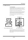
C bus is a simple, two-wire bus for transferring data between ICs. Since it
requires only two lines, a serial data line (SDA) and a serial clock line (SCL), it
minimizes interconnections so ICs have fewer pins and there are less PCB tracks.
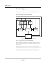
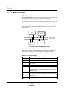
The result is smaller and less expensive PCBs. Figure 13-1 shows a typical I
2
C
bus application.
In an I
2
C bus system, devices are considered as masters or slaves when performing
data transfers. A master is the device that initiates a data transfer on the bus and
generates the clock signals to permit that transfer. At that time, any device
addressed is considered a slave. Table 13-1 defines some I
2
C bus terminology.
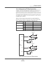
Figure 13-1 Example of I
2
C Bus Application
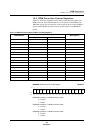
Table 13-1 I
2
C Bus Terminology
Term Description
Transmitter The device that sends the data to the bus
Receiver The device that receives the data from the bus
Master The device that initiates a transfer, generates clock signals, and termi-
nates a transfer
Slave The device addressed by a master
Multimaster More than one device capable of controlling the bus can be connected
to it. More than one master can attempt to control the bus at the same
time without corrupting the message. The system is not dependent on
any single master.
Arbitration Procedure to ensure that, if more than one master simultaneously tries
to control the bus, only one is allowed to do so and the message is not
corrupted. The device that loses arbitration becomes the slave of the
device that wins.
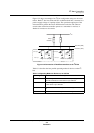
Synchronization Procedure to synchronize the clock signals of two or more devices
MCU 1
Display
Serial memory
MCU 2
Data line (SDA)
Clock line (SCL)