


Serial Interfaces
Serial Interface Setup Examples
MN102H75K/F75K/85K/F85K LSI User Manual Panasonic Semiconductor Development Company
131
Panasonic
5.6 Serial Interface Setup Examples
5.6.1 Setting Up UART Transmission Using Serial Interface 0
You must use an 8-bit timer to
set the transfer clock. See sec-
tion 5.6.3, “Setting Up the Serial
Interface Clock,” on page 135,
for an example setup.
This example illustrates serial transmission in the UART mode with the fol-
lowing settings:
♦ B
OSC
= 24 MHz
♦ Baud rate = 9600 bps (transfer clock set up with timer 0)
♦ 8-bit character length
♦ Two stop bits
♦ Odd parity
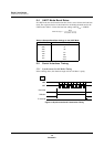
When a transmission end interrupt occurs, the next data byte is loaded.
Data transmission starts when the CPU writes data to the SC0TRB register. The
transmission start is synchronized to timer 0 underflow. An interrupt occurs when
transmission ends, and the next data byte is written to SC0TRB. If the application
does not use interrupts, it must poll the SC0TBY flag of the SC0STR register. It
can write the transmission data when SC0TBY is 0.
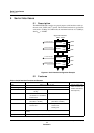
■
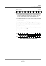
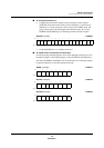
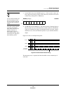
To set up the output port:
Set the P5MD5 bit of the port 5 output mode register (P5MD) to 1. This selects
the SBO0 pin as the serial interface output port.
P5MD (example) x’00FFFA’
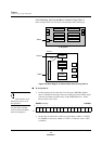
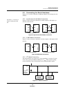
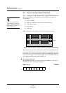
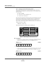
Figure 5-9 Block Diagram of UART Transmission Using Serial Interface 0
SBO0
P0
P2
P4
P6
CORE
Interrupts
Timers 0-1
Timers 2-3
ROM, RAM
Bus Controller
Serial I/Fs
ADC
P1
P3
P5
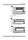
Bit:76543210
P5
MD7
P5
MD6
P5
MD5
P5
MD4
P5
MD3
P5
MD2
P5
MD1
P5
MD0
Setting:01000000