


Serial Interfaces
Serial Interface Control Registers
MN102H75K/F75K/85K/F85K LSI User Manual Panasonic Semiconductor Development Company
141
Panasonic
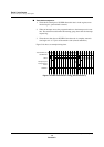
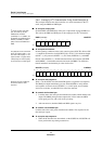
SCnICM: Serial port n I
2
C mode select
0: I
2
C mode off
1: I
2
C mode on
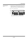
SCnLN: Serial port n character length
0: 7-bit
1: 8-bit
SCnPTY[2:0]: Serial port n parity bit select
000:None
001:Reserved
010:Reserved
011:Reserved
100:0 (output low)
101:1 (output high)
110:Even (1s are even)
111:Odd (1s are odd)
SCnSB: Serial port n stop bit select (UART mode only)
0: 1-bit
1: 2-bit
SCnS[1:0]: Serial port n clock source select
The 00 and 10 settings are reserved in UART and I
2
C modes.
00: SBTn pin
01: Timer 0 underflow × 1/8
10: Timer 1 underflow × 1/2
11: Timer 1 underflow × 1/8
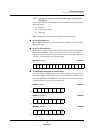
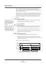
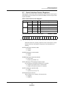
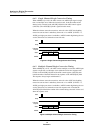
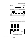
SC0TRB/SC1TRB: Serial Port n Transmit/Receive Buffer x’00FD82’/x’00FD88’
Data transmission begins when the CPU writes data to SCnTRB.
The CPU retrieves the data by reading SCnTRB. SCnTRB has two respec-
tive buffers, for transmission and for reception. The buffers for reception is
consist of two buffers and the received data is set to SCnTRB after the
reception ends, and held until that of the next data ends
Over-run-error occurs if SCnTRB is not read, before the reception of the
next data ends (See 5-5)
When the received data is set to SCnTRB, reception end interrupt occurs
and SCnRXA flag of SCnTRB register is set to 1.
During 7-bit transfers, the most significant bit (bit 7) of SCnTRB is always
0.
The reset value of SC0TRB is undefined.
Bit:76543210
SCn
TRB7
SCn
TRB6
SCn
TRB5
SCn
TRB4
SCn
TRB3
SCn
TRB2
SCn
TRB1
SCn
TRB0
Reset:————————
R/W: R/W R/W R/W R/W R/W R/W R/W R/W