


Low-Power Modes
CPU Modes
Panasonic Semiconductor Development Company MN102H75K/F75K/85K/F85K LSI User Manual
72
Panasonic
3 Low-Power Modes
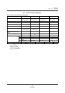
The MN102H75K/85K provides two ways to reduce power consumption, con-
trolling CPU operating and standby modes to cut overall consumption and
shutting down unused functions by stopping the system clock supplied to them.
3.1 CPU Modes
3.1.1 Description
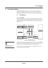
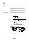
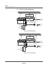
The MN102H75K/85K has two CPU operating modes, NORMAL and SLOW,
and two CPU standby modes, HALT and STOP. Effective use of these modes can
significantly reduce power consumption. Figure 3-1 shows the CPU states in the
different modes.
You cannot enter STOP mode
from NORMAL mode.
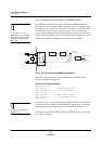
The CPU mode control register (CPUM) controls transitions between NORMAL
and SLOW modes and from NORMAL and SLOW modes to the standby modes.
A normal reset or an interrupt wakes the MCU from a standby mode.
Note that you cannot invoke the STOP mode from NORMAL mode. You can
only enter STOP from the SLOW mode.
Figure 3-1 CPU State Changes
NORMAL Mode
Clock to CPU: 24 MHz
System clock: 12 MHz
CPU and PLL on
SLOW Mode
Clock to CPU: 4 MHz
System clock: 2 MHz
CPU on, PLL on
Program
(Write to CPUM register)
Program
(Write to CPUM register)
STOP Mode
Clock to CPU: off
System clock: off
CPU and PLL off
HALT Mode
Clock to CPU: 4 MHz
System clock: 2 MHz
CPU and PLL off
Program
(Write to CPUM
register)
Interrupt
Program
(Write to CPUM
register)
Interrupt
Program
(Write to CPUM
register)
Interrupt
Clock to CPU: 24 MHz
System clock: 12 MHz
CPU stopped, PLL on
Program
(Write to CPUM register)
IDLE State
Clock to CPU: 24 MHz
System clock: 12 MHz
CPU and PLL on