


Serial Interfaces
Serial Interface Setup Examples
Panasonic Semiconductor Development Company MN102H75K/F75K/85K/F85K LSI User Manual
134
Panasonic
5.6.2 Setting Up Synchronous Serial Reception Using Serial
Interface 0
This example illustrates serial reception in the synchronous serial mode with the
following settings:
♦ LSB first
♦ 8-bit character length
♦ Odd parity
When a reception end interrupt occurs, the CPU reads the data byte.
■
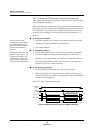
To set up the input port:
Set the P5DIR7 bit of the port 5 I/O control register (P5DIR) to 0. This sets the
SBT0 pin to input.
■
To set up serial interface 0:
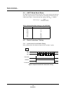
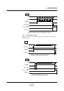
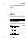
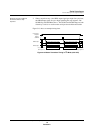
Configure the reception settings in the serial port 0 control register (SC0CTR).
Select timer 0 underflow x 1/8 as the serial port 0 clock source. Select timer 0
underflow x 1/8 as the serial port 0 clock source. Select synchronous serial mode,
odd parity, 8-bit data length, and LSB-first output.
SC0CTR (example) x’00FD80’
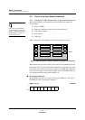
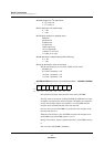
■ To enable serial 0 transmission end interrupts:
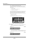
Cancel all existing interrupt requests. Next, set the interrupt priority level of 5 in
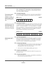
the ANLV[2:0] bits of the ANICH register, set the SCR0IE bit of SCR0ICH to 1,
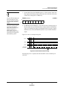
and set the SCR0IR bit of SCR0ICL to 0. From this point on, an interrupt request
is generated whenever a serial data reception ends.
ANICH: (example) x’00FC81’
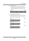
SCR0ICL (example) x’00FC84’
SCR0ICH (example) x’00FC85’
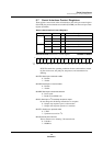
Bit:1514131211109876543210
SC0
TEN
SC0
REN
SC0
BRE
SC0
I2CS
SC0
PTL
—
SC0
OD
SC0
I2CM
SC0
LN
SC0
PTY2
SC0
PTY1
SC0
PTY0
SC0
SB
—
SC0
S1
SC0
S0
Setting:1100100011110001
Bit:76543210
— ANLV2 ANLV1 ANLV0 — — — ANIE
Setting:01010000
Bit:76543210
———
SCR0
IR
———
SCR0
ID
Setting:00000000
Bit:76543210
———————
SCR0
IE
Setting:00000001