


Closed-Caption Decoder
Functional Description
Panasonic Semiconductor Development Company MN102H75K/F75K/85K/F85K LSI User Manual
228
Panasonic
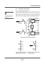
9.3 Functional Description
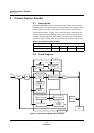
9.3.1 Analog-to-Digital Converter
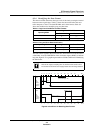
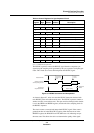
The constants shown in figures 9-2
to 9-4 are recommended values
only. Operation at these values is
not guaranteed.
The analog-to-digital converter (ADC) converts the clamped video signal to 8-bit
digital data using a 12-MHz sampling clock. Figure 9-2 shows an example con-
figuration using the recommended external pin connections. In this example, both
caption decoders are used. Figure 9-3 shows the recommended connection when
neither decoder is used, and figure 9-4 shows that when only CCD0 is used.
Figure 9-2 Recommended ADC Configuration
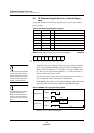
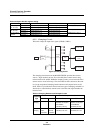
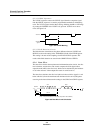
Figure 9-3 External Connection with
Both CCD0 and CCD1 Unused
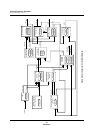
Figure 9-4 External Connection with
Only CCD1 Unused
+
+
560 pF
240 Ω
A/D
VREFH
VREFL
CVBS0
CVBS1
CLL
CLH
VREFHS
VREFLS
IN
OUT
CLK
Power Down
ADDATA[7: 0]
A/D
VREFH
VREFL
IN
OUT
CLK
Power Down
ADDATA[7: 0]
+
+
1 µF
1 µF
1 µF
1 µF
+
+
Clamping
circuit
560 pF
240 Ω
ADC0ON
(PCNT0: x’00FF90’, bit 4)
VBI0OFF
(PCNT0: x’00FF90’, bit 0)
3.3 V
3.3 V
3.3 V
6.8 kΩ
8.2 kΩ
33 kΩ
18 kΩ
1 kΩ
1 kΩ
1µF
1 µF
3.3 V
3.3 V
8.2 kΩ
18 kΩ
VIDEO IN 0
VIDEO IN 1
Low pass filter
Low pass filter
f
SYSCLK
(12 MHz)
ADC1ON
(PCNT0: x’00FF90’, bit 5)
VBI1OFF
(PCNT0: x’00FF90’, bit 1)
1kΩ
VREFHS
CVBS0
(Used as P31)
CVBS1
(Used as P32)
VREFLS
CLH
(Used as P30)
CLL
(Used as P33)
+
VIDEO IN
1 µF
VREFHS
CVBS0
CVBS1
(Used as P32)
VREFLS
External
circuit
33 kΩ
6.8 kΩ
CLL
CLH