


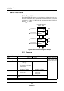

Serial Interfaces
Serial Interface Setup Examples
MN102H75K/F75K/85K/F85K LSI User Manual Panasonic Semiconductor Development Company
135
Panasonic
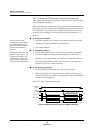
5.6.3 Setting Up the Serial Interface Clock
This example demonstrates how to set up a 19,200 bps transfer clock for the
UART interface by using timer 1 to divide B
OSC
/4 by 39. The example uses the
following settings:
♦ B
OSC
= 24 MHz
♦ Clock source = timer 1 underflow x 1/8
♦ Transfer clock = baud rate x 8
The serial interface determines the baud rate from the 8-bit underflow. Set up the
transfer clock by making the timer 1 underflow either two or eight times the
desired baud rate. The serial interface divides the timer underflow by two or
eight. (Always select divide-by-eight for UART transactions.) For a baud rate of
19,200, since B
OSC
/4 = 6 MHz,
6 MHz/39/8 = 19230.77 bps
This means that the timer 1 underflow must be divided by 39.
■
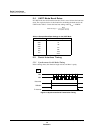
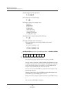
To set timer 1:
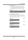
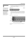
1. Disable timer 1 counting in the timer 1 mode register (TM1MD). This step is
unnecessary immediately after a reset, since TM1MD resets to 0.
TM1MD (example) x’00FE21’
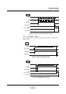
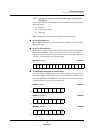
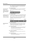
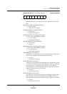
2. Set the divide-by ratio for timer 1. To divide B
OSC
/4 by 39, write x’26’ to the
timer 1 base register (TM1BR). (The valid range for TM1BR is 0 to 255.)
TM1BR (example) x’00FE11’
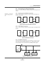
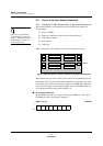
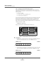
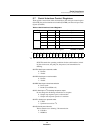
Figure 5-11 Block Diagram of Serial Interface Clock
P0
P2
P4
P6
CORE
Interrupts
Timers 0-1
Timers 2-3
Timers 4-5
P1
P3
P5
ROM, RAM
Bus Controller
Serial I/Fs
ADC
Bit:76543210
TM1
EN
TM1
LD
————
TM1
S1
TM1
S0
Setting:00000000
Bit:76543210
TM1
BR7
TM1
BR6
TM1
BR5
TM1
BR4
TM1
BR3
TM1
BR2
TM1
BR1
TM1
BR0
Setting:00100110