


Serial Interfaces
Serial Interface Control Registers
Panasonic Semiconductor Development Company MN102H75K/F75K/85K/F85K LSI User Manual
140
Panasonic
5.7 Serial Interface Control Registers
Three registers control each of the serial interfaces: the serial port control register
(SCnCTR), the serial transmit/receive buffer (SCnTRB), and the serial port status
register (SCnSTR).
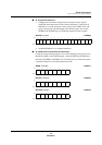
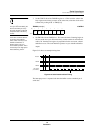
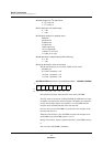
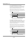
SC0CTR/SC1CTR: Serial Port n Control Register x’00FD80’/x’00FD88’
SC0CTR controls the operating conditions for the serial interface, includ-
ing the clock source, the parity bit, the protocol, and transmit/receive
enabling.
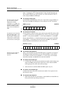
SCnTEN: Serial port n transmit enable
0: Disable
1: Enable
SCnREN: Serial port n receive enable
0: Disable
1: Enable
SCnBRE: Serial port n break transmission
0: Don’t break
1: Break (Force SBOn to 0)
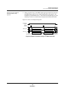
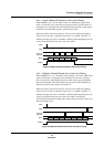
SCnIIC: Serial port n I
2
C start/stop sequence output
Do not change this bit during transmission or reception.
0: Output stop sequence upon 1-to-0 transition
1: Output start sequence upon 0-to-1 transition
SCnPTL: Serial port n protocol select
0: UART
1: Synchronous serial or I
2
C
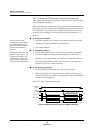
SCnOD: Serial port n bit order
This bit must be set to 0 during 7-bit transmission.
0: LSB first
1: MSB first
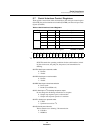
Table 5-3 Serial Interface Control Registers
Register Address R/W Description
Serial I/F
0
SC0CTR x’00FD80’ R/W Serial port 0 control register
SC0TRB x’00FD82’ R/W Serial port 0 transmit/receive buffer
SC0STR x’00FD83’ R Serial port 0 status register
Serial I/F
1
SC1CTR x’00FD88’ R/W Serial port 1 control register
SC1TRB x’00FD8A’ R/W Serial port 1 transmit/receive buffer
SC1STR x’00FD8B’ R Serial port 1 status register
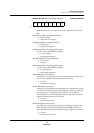
Bit:1514131211109876543210
SCn
TEN
SCn
REN
SCn
BRE
SCn
IIC
SCn
PTL
—
SCn
OD
SCn
ICM
SCn
LN
SCn
PTY2
SCn
PTY1
SCn
PTY0
SCn
SB
—
SCn
S1
SCn
S0
Reset:0000000000000000
R/W: R/W R/W R/W R/W R/W R R/W R/W R/W R/W R/W R/W R/W R R/W R/W