


Interrupts
Interrupt Setup Examples
MN102H75K/F75K/85K/F85K LSI User Manual Panasonic Semiconductor Development Company
43
Panasonic
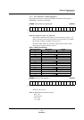
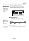
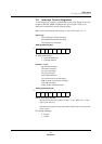
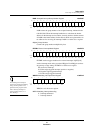
The main program normally gen-
erates and branches to the inter-
rupt start address.
If the CPU accepts an interrupt, the program branches to address x’080008’.
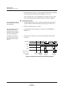
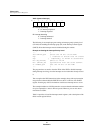
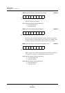
The oscillator delay timer shares the counter for the watchdog timer. The
oscillator delay timer is activated when the circuit exits the STOP mode, so the
program must clear the WDID flag to 0 prior to entering the STOP mode. It must
also reclear WDID after returning to NORMAL mode. For further details, see
section 2-6, “Standby Function,” in the MN10200 Series Linear Addressing
Version LSI User Manual.
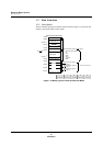
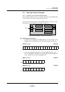
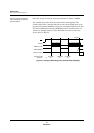
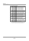
Figure 2-7 Timing for Watchdog Timer Interrupt Setup (Example)
RST
WD count
NWDEN (CPUM)
WDID (WDICR)
Interrupt servicing
CPUM (W) CPUM (W) CPUM (W)
(1) (2) (3) (2)
Clear
Overflow
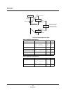
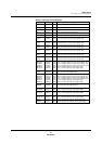
Registers [R/W]
Sequence