


Interrupts
Interrupt Control Registers
Panasonic Semiconductor Development Company MN102H75K/F75K/85K/F85K LSI User Manual
44
Panasonic
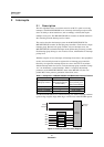
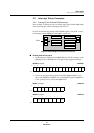
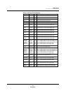
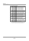
2.3 Interrupt Control Registers
A control register is assigned to each interrupt vector group. Except for the class
0 registers (WDICR, PIICR, and EIICR), the control registers allow you to
enable and set the priority level for interrupt groups.
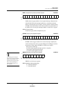
Below is the general format of the registers in class 0 and classes 1 to 11.
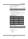
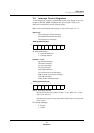
Class 0 (X):
WD (watchdog overflow interrupts)
PI (undefined instruction interrupts)
EI (interrupt error interrupts)
XICR (System Interrupt)
ID: Interrupt detect flag
0: Interrupt undetected
1: Interrupt detected
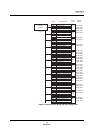
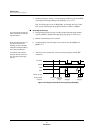
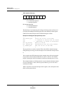
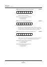
Classes 1–11 (X):
IQ (external interrupts)
TM (timer interrupts)
SC (serial interrupts)
I2C (I2C interrupts)
OSD (OSD interrupts)
AN (A/D conversion end interrupts)
RMC (remote signal receive interrupts)
VBI (VBI interrupts)
ADM (address match interrupts)
XnICH (System Interrupt)
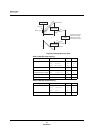
LV[2:0]: Interrupt priority level
Sets the priority from 0 to 6 (000 = 0, 001 = 1, etc.). When LV = 7, inter-
rupts are not serviced.
Note that some registers do not contain the LV field. In this case, these bits
always read 0.
IE: Interrupt enable flag
0: Disable
1: Enable
Bit:76543210
———————ID
Bit:76543210
— LV2 LV1 LV0 — — — IE