


Timers
16-Bit Timer Setup Examples
MN102H75K/F75K/85K/F85K LSI User Manual Panasonic Semiconductor Development Company
105
Panasonic
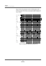
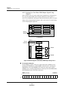
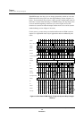
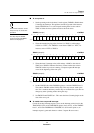
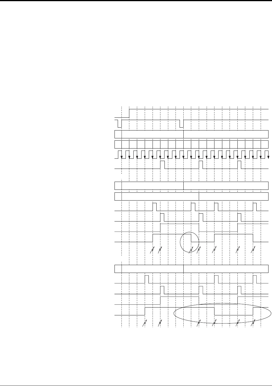
With PWM output, the duty cycle can change dynamically, which can cause the
PWM waveform to skip a pulse (see the single buffering section of figure 4-34
below). To prevent these misses, timers 4 and 5 provide a double-buffer mode. In
this mode, no matter what the timing of a TMnCB change, the duty change does
not occur until the beginning of the next cycle, and no signals are lost. Per-
formance is assured even when the output switches from all 1s to all 0s (see the
double buffering section of figure 4-34 below).
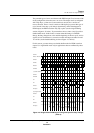
For this reason, you must always use double-buffer mode for PWM waveform
output. Use single-buffer mode only in applications that are unaffected by this
issues.
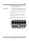
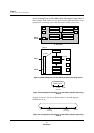
Figure 4-34 Two-Phase PWM Output Timing with Dynamic Duty Changes
(Timer 4)
012340 01234012340123
B
A
B
A
B B
A
31
31
31
31
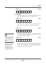
No PWM or interrupt errors
TM4EN
Write to TM4CB
TM4CB
TM4BC
B
OSC
/4
CLRBC4
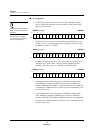
(1) Double buffering
TM4CB
TM4CBX
B4
A4
TM4OA
TM4OB
Interrupts
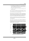
(2) Single buffering
TM4CB
B4
A4
TM4OA
TM4OB
Interrupts
A
B
A
B B
A
Lost interrupt, causing a PWM output error