


General Description
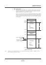
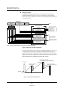
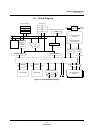
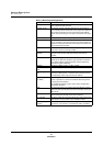
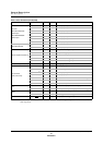
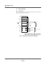
Block Diagram
MN102H75K/F75K/85K/F85K LSI User Manual Panasonic Semiconductor Development Company
29
Panasonic
Table 1-2 Block Diagram Explanation
Block Description
Clock generator An oscillation circuit connected to an external crystal supplies the
clock to all blocks within the CPU.
Program counter The program counter generates addresses for queued instruc-
tions. Normally it increments based on the sequencer indications,
but for branch instructions it is set as the branch head address,
and for interrupt servicing, it is set as the result of the ALU opera-
tion.
Instruction queue This block contains up to four bytes of prefetched instructions.
Instruction decoder The instruction decoder decodes the contents of the instruction
queue, generates, in the proper sequence, the control signals nec-
essary for executing the instruction, and controls every block in the
chip to execute the instruction.
Quick decoder This block decodes instructions that are 2 bytes or larger in at a
much faster rate than previously possible.
Instruction execution
controller
This block controls the operation of every block within the CPU
using the results from the instruction decoder and interrupt
requests.
ALU Arithmetic and logic unit. This block calculates the operand
addresses for arithmetic operations, logic operations, shift opera-
tions, relative indirect register addressing, indexed addressing,
and indirect register addressing.
Multiplier This block multiplies 16 bits × 16 bits = 32 bits.
Internal ROM and
RAM
These memory blocks contain the program, data, and stack areas.
Address registers
(An)
The address registers store the addresses in memory to be
accessed in data transfers. In relative indirect, indexed, and indi-
rect addressing modes, they store the base address.
Operation registers
(Dn, MDR)
The data registers store data to be transferred to memory and
results of operations. In indexed and indirect addressing modes,
they store the offset address.
The multiplication/division register stores data for multiplication
and division operations.
PSW The processor status word contains flags that indicate the status
of the CPU interrupt controller and provide information about oper-
ation results.
Interrupt controller This block detects interrupt requests from peripheral function
blocks and requests the CPU to service the interrupt.
Bus controller This block controls the connection between the CPU’s internal and
external buses. It also contains a bus arbitration function.
Internal peripheral
functions
MN102H series devices contain a wide range of internal periph-
eral devices, such as timers, serial interfaces, ADCs, and DACs.