


Timers
16-Bit Timer Setup Examples
Panasonic Semiconductor Development Company MN102H75K/F75K/85K/F85K LSI User Manual
108
Panasonic
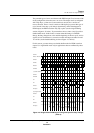
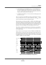
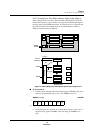
4.11.5 Setting Up a Two-Phase Capture Input Using Timer 4
In this example, timer 4 is used to divide the timer 0 underflow by 65,536 and
measure the number of cycles from the rising edge of the TM4IA input signal to
the rising edge of the TM4IB input signal. An interrupt occurs on capture B and
the software calculates the number of cycles by subtracting the contents of
TMnCA from the contents of TMnCB.
■
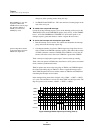
To set up timer 0:
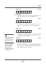
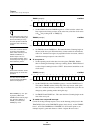
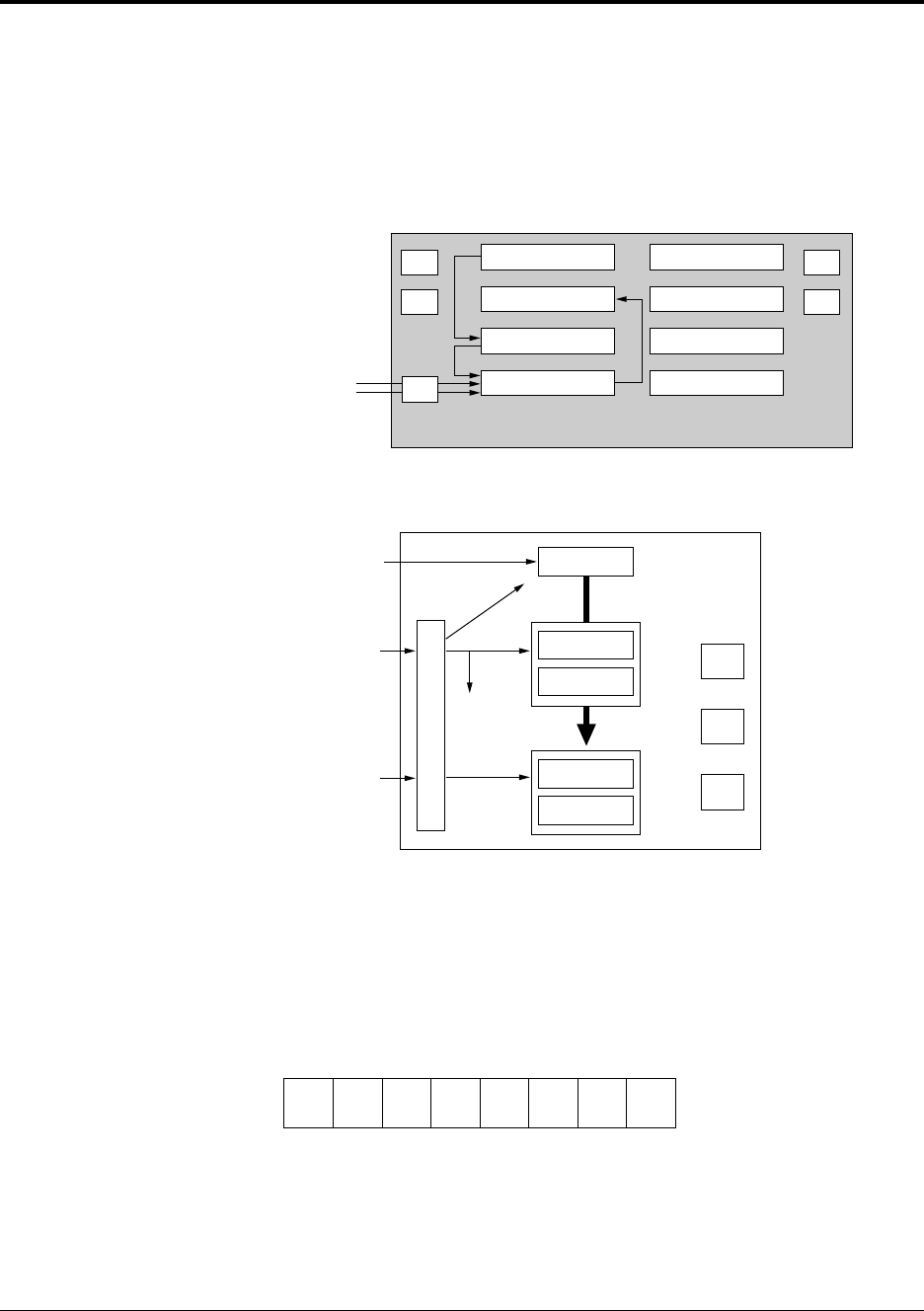
1. Disable timer 0 counting in the timer 0 mode register (TM0MD). This step is
unnecessary immediately after a reset, since TM0MD resets to 0.
TM0MD (example) x’00FE20’
2. Set the divide-by ratio for timer 0. To divide B
OSC
/4 by two, write x’01’ to
the timer 0 base register (TM0BR). (The valid range for TM0BR is 0 to
255.)
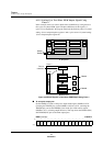
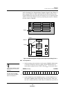
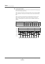
A. Chip Level
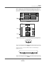
B. Block Level
Figure 4-37 Block Diagram of Two-Phase Capture Input Using Timer 4
TM4IA
TM4IB
P3
P6
P4
P5
CORE
Interrupts
Timers 0-3
Timers 4-5
ROM, RAM
Bus Controller
Serial I/Fs
ADC
P2
TM4IA
Interrupt B
Timer 0
underflow
up
TM4BC
Timer 4
TM4CA
TM4CB
TM4IB
TQ
TQ
R
S
Q
Controller
Bit:76543210
TM0
EN
TM0
LD
————
TM0
S1
TM0
S0
Setting:000000——