


Low-Power Modes
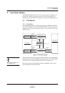
CPU Modes
Panasonic Semiconductor Development Company MN102H75K/F75K/85K/F85K LSI User Manual
74
Panasonic
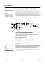
3.1.3 Notes on Invoking and Exiting STOP and HALT Modes
■ When invoking STOP and HALT modes...
To reduce power consumption before invoking the STOP or HALT mode, stop
current flow from output pins and stabilize the input level of input pins. For
output pins, either match the output level to the external level or set the pin to
input. For input pins, ensure that the external level is fixed. To further reduce
power consumption, shut down unnecessary functions through the control reg-
isters. (See section 3.2, “Turning Individual Functions On and Off,” on page 75.)
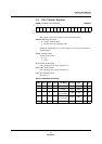
Before entering the STOP mode, set all of the bits shown in table 3-1 to disable
all of these functions. Disable all functions in the NORMAL mode except the
PLL circuit, which you can only shut down once you have entered the SLOW
mode.
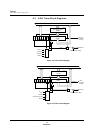
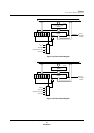
Using OSDX clock (both an LC
blocking oscillator and external
source), OSDXI and OSDXO
must be set to port (P46, P45)
and output ’H’ before invoking
STOP mode.
To allow the MCU to exit the STOP or HALT mode on reset or interrupt, you
must set the interrupt registers before you invoke the standby mode. To specify a
particular interrupt vector as the signal for waking up, enable that vector in the
interrupt registers. (For more information on controlling interrupts, see “section
2, “Interrupts,” on page 37.)
■
When exiting STOP and HALT modes...
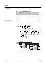
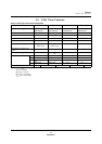
The MCU exits STOP and HALT modes on reset or interrupt. For information on
exiting on interrupt, see Figure 3-1, “CPU State Changes,” on page 72. When the
MCU exits on reset, it always exits to SLOW mode.