


General Description
Pin Descriptions
Panasonic Semiconductor Development Company MN102H75K/F75K/85K/F85K LSI User Manual
34
Panasonic
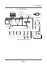
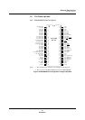
■ Considerations for power supply, clock, and reset pins
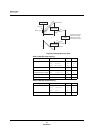
■ Connection the PLL circuit
The MN102H75K/85K contains an internal PLL circuit. To use this circuit, you
must connect it to an external (lag-lead) filter.
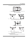
Note: If the circuit uses the same power supply for digital and analog supplies, connect
the pins in the location closest to the power supply.
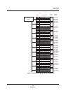
Figure 1-11 Power Supply Wiring
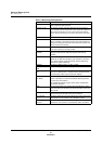
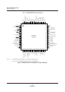
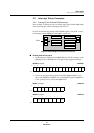
Note: The capacitance values vary depending on the oscillator.
Figure 1-12 OSC1 and OSC2 Connection Examples
Figure 1-13 Reset Pin Connection Example 1
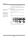
Note: The capacitance values vary depending on the oscillator.
Figure 1-14 OSDXI and OSDXO Connection Examples
Power
Supply
V
DD
V
SS
V
DD
V
SS
AV
DD
AV
SS
MN102H75K
MN102H85K
OSC1
OSC2
4 MHz
OSC1
0.1 µF
OSC2
4 MHz
Oscillation
Circuit
10 kΩ - 50 kΩ
+
-
10 µF - 100 µF
RST
S
W
Di
OSDXI
OSDXO
16MHz - 48MHz
OSDXI
OSDXO
16MHz - 48MHz
Oscillation
Circuit