


Timers
8-Bit Timer Description
MN102H75K/F75K/85K/F85K LSI User Manual Panasonic Semiconductor Development Company
77
Panasonic
4Timers
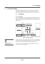
4.1 8-Bit Timer Description
The MN102H75K/85K contains four 8-bit timers that can serve as interval
timers, event timer/counters, clock generators (divide-by-2 output of the
underflow), reference clocks for the serial interfaces, or start timers for A/D con-
versions. The clock source can be the internal clock (oscillator frequency divided
by 2) or the external clock (1/4 or less the oscillator frequency input). A timer
interrupt is generated by a timer underflow.
All passages below assume a
clock B
OSC
of 24 MHz.
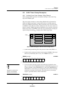
The 8-bit timers are cascadable into true 16-bit timers. For instance, if you
cascade timers 0 and 1, timer 0 sends cascaded output to timer 1. The result is
true 16-bit division, rather than two successive 8-bit divisions.
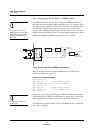
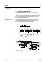
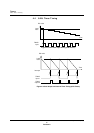
Figure 4-1 Timer Configuration Examples
Note: B
OSC
= 24 MHz
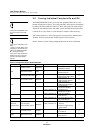
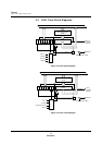
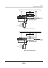
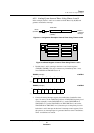
Figure 4-2 Block Diagram of 8-Bit Timers
Cascading Connections
8-bit x 4
16-bit 8-bit 8-bit 8-bit 8-bit 16-bit
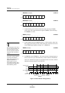
Clock output
Interval
timer
Sync.
transfer
clock
UART
transfer
clock
Event
timer
Event
timer
Configuration example
TM0UDIR
TM1UDIR
TM2UDIR
(To 16-bit timer, serial I/F)
(To 16-bit timer, serial I/F)
B
OSC
/4
TM2
TMIA
TMIB
TMIC
TMID
UDF
TMIO
TM0I
TM0
TMIA
TMIB
TMIC
TMID
UDF
TMIO
TM1
TMIA
TMIB
TMIC
TMID
UDF
TMIO
B
OSC
/64
B
OSC
/256
B
OSC
/512
TM3
TMIA
TMIB
TMIC
TMID
UDF
TMIO
TM1I
TM1O
TM0O
TM3UDIR
A/D conversion start