


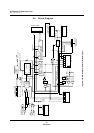
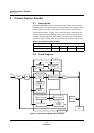

IR Remote Signal Receiver
IR Remote Signal Receiver Operation
MN102H75K/F75K/85K/F85K LSI User Manual Panasonic Semiconductor Development Company
221
Panasonic
8.3.5 Generating Interrupts
The IR remote signal receiver has four interrupt vectors: leader detection, trailer
detection, 8-bit data reception detection, and pin edge detection. This section
describes the operation for each of them.
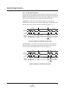
8.3.5.1 Leader Detection
An interrupt occurs when the circuit detects a data leader. It detects leaders by
testing the interval between remote signal edges. Table 8-3 shows the conditions.
8.3.5.2 Trailer Detection
An interrupt occurs when the 6-bit counter overflows.
8.3.5.3 8-Bit Data Reception Detection
An interrupt occurs when the microcontroller loads 8-bit received data to the
reception data transfer register, RMTR.
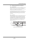
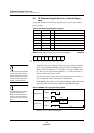
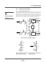
8.3.5.4 Pin Edge Detection
An interrupt occurs when the remote signal input pin, RMIN, is asserted. The
POLSEL bit of RMIR sets the polarity of RMIN.
The detection output for all four interrupt vectors is an active high pulse asserted
at intervals of 1/f
SYSCLK
. Bits 3 to 0 of the RMIR register control the interrupt
vectors individually. A 0 disables the interrupt vector and a 1 enables it.
A remote signal interrupt sets the RMCIR flag of the RMCICL interrupt register
(x’00FC76’).
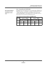
Table 8-3 Leader Detection Conditions
Format Edge Interval
HEAMA data leader (
n
- 4)T
S
≤ interval < (n + 4)T
S
(1)
5-/6-bit data leader 28T
S
≤ interval < 36T
S
Note: 1. n = the leader value set in LD[3:0] of the RMLD register.
Note: 1/f
SYSCLK
= 1/12 MHz = 0.083 µs
Figure 8-6 Pin Edge Detection
RMIN input
positive-edge-triggered
(POLSEL=0)
RMIN input
negative edge-triggered
(POLSEL=1)
Edge detection output
1/f
SYSCLK
1/f
SYSCLK