


Analog-to-Digital Converter
A/D Conversion Timing
MN102H75K/F75K/85K/F85K LSI User Manual Panasonic Semiconductor Development Company
145
Panasonic
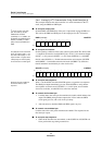
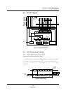
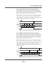
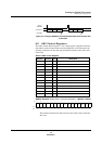
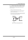
6.4.2 Single Channel/Single Conversion Timing
When ANMD[1:0] = b’00’, the ADC converts one ADIN input signal a single
time. An interrupt occurs when the conversion ends. Load the number of the
channel to be converted to the AN1CH[3:0] field of the ADC control register
(ANCTR). (The ANNCH[3:0] field is ignored in this mode.)
When the software starts the conversion, write a 0 to the ANTC bit (disabling
conversion start at timer 1 underflow), then write a 1 to ANEN. (If ANTC = 1,
ANEN goes high upon a timer 1 underflow.) ANEN remains high during the con-
version, then clears to 0 when the conversion ends.
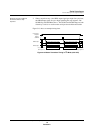
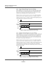
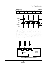
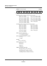
6.4.3 Multiple Channel/Single Conversion Timing
When ANMD[1:0] = b’01’, the ADC converts multiple, consecutive ADIN input
signals a single time. An interrupt occurs when the conversion sequence ends.
Load 0s to the AN1CH[3:0] field of the ADC control register (ANCTR), then
load the number of the final channel in the sequence to the ANNCH[3:0] field.
The sequence always begins with channel 0.
When the software starts the conversion, write a 0 to the ANTC bit (disabling
conversion start at timer 1 underflow), then write a 1 to ANEN. (If ANTC = 1,
ANEN goes high upon a timer 1 underflow.) ANEN remains high during the con-
version, then clears to 0 when the conversion sequence ends. Note that the
AN1CH[3:0] field holds the number of the channel being converted. It clears to 0
when the sequence ends.
Figure 6-4 Single Channel/Single Conversion Timing
Figure 6-5 Multiple Channel/Single Conversion Timing
Stop
Start
Interrupt
request
ANEN
State
Channel 0
conversion
Channel 1
conversion
Channel 2
conversion
Stop
Start
Interrupt
request
ANEN
State
Channel 0
conversion
Channel 1
conversion
Channel 2
conversion