


Page 22-34
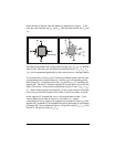
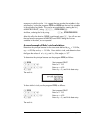
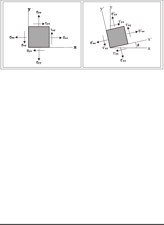
shows the state of stresses when the element is rotated by an angle φ. In this
case, the normal stresses are σ’
xx
and σ’
yy
, while the shear stresses are τ’
xy
and
τ’
yx
.
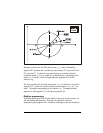
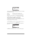
The relationship between the original state of stresses (σ
xx
, σ
yy
, τ
xy
, τ
yx
) and the
state of stress when the axes are rotated counterclockwise by f (σ’
xx
, σ’
yy
, τ’
xy
,
τ’
yx
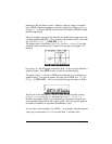
), can be represented graphically by the construct shown in the figure below.
To construct Mohr’s circle we use a Cartesian coordinate system with the x-axis
corresponding to the normal stresses (σ), and the y-axis corresponding to the
shear stresses (τ). Locate the points A(σ
xx
,τ
xy
) and B (σ
yy
, τ
xy
), and draw the
segment AB. The point C where the segment AB crosses the σ
n
axis will be the
center of the circle. Notice that the coordinates of point C are (½⋅(σ
yy
+ σ
xy
),
0). When constructing the circle by hand, you can use a compass to trace the
circle since you know the location of the center C and of two points, A and B.
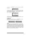
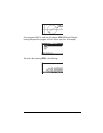
Let the segment AC represent the x-axis in the original state of stress. If you
want to determine the state of stress for a set of axes x’-y’, rotated
counterclockwise by an angle
φ
with respect to the original set of axes x-y, draw
segment A’B’, centered at C and rotated clockwise by and angle
2φ
with respect
to segment AB. The coordinates of point A’ will give the values (σ’
xx
,τ’
xy
), while
those of B’ will give the values (σ’
yy
,τ’
xy
).