WXB Hot-Plug
8-14 Intel® 460GX Chipset Software Developer’s Manual
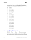
for unpopulated slots and slots with open switches. The set of usable LED Control bits is
determined by the strapping values on the P(A,B)HSIL, P(A,B)HSOL, and P(A,B)HSOC inputs.
Unsupported slots in a system do not have writeable LED Control bits. LEDs are not affected by
changes to these register bits until a SOGO is initiated following the changes.
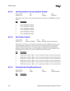
Bits
Description
31:30 reserved (0)
29 Slot F Amber LED, msb
28 Slot E Amber LED, msb
27 Slot D Amber LED, msb
26 Slot C Amber LED, msb
25 Slot B Amber LED, msb
24 Slot A Amber LED, msb
23:22 reserved (0)
21 Slot F Amber LED, lsb
20 Slot E Amber LED, lsb
19 Slot D Amber LED, lsb
18 Slot C Amber LED, lsb
17 Slot B Amber LED, lsb
16 Slot A Amber LED, lsb
15:14 reserved (0)
13 Slot F Green LED, msb
12 Slot E Green LED, msb
11 Slot D Green LED, msb
10 Slot C Green LED, msb
9 Slot B Green LED, msb
8 Slot A Green LED, msb
7:6 reserved(0)
5 Slot F Green LED, lsb
4 Slot E Green LED, lsb
3 Slot D Green LED, lsb
2 Slot C Green LED, lsb
1 Slot B Green LED, lsb
0 Slot A Green LED, lsb
8.2.5 Hot-Plug Interrupt Input and Clear
Address Offset: 08h Size: 32 bits
Default Value: Varies Attribute: Read/Write Clear (Pwr Gd Rst Only)
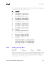
These bits indicate the state of the interrupt capable inputs when no interrupt is pending. When a
hot-plug general interrupt changes state (either high to low or low to high), and the bit is not
masked in the Interrupt Mask register, an interrupt is generated and the state of that input is latched


