IFB Usage Considerations
10-14 Intel® 460GX Chipset Software Developer’s Manual
10.5.9 Example Configurations
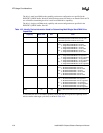
This section provides examples of drive configurations on a IFB-based system.
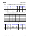
10.5.9.1 Example #1: Ultra DMA/33 Configuration
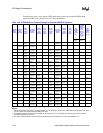
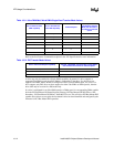
In the above configuration, since both drives support Ultra DMA, Ultra DMA will be enabled on
each of the drives: Ultra DMA Mode 2 for Drive 0 and Ultra DMA Mode 1 for Drive 1. Non-ultra
DMA and Fast PIO support will be enabled on each drive as well.
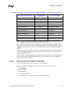
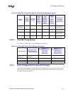
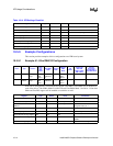
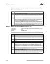
Table 10-14. IFB Settings Checklist
Register Type Offset Value Comments
PCI Command Register PCI 04h 0005h Ensure that bits 0 and 2 are ‘1’
PCI Master Latency Timer PCI 0Dh
PCI Bus Master IDE Base I/O Address PCI 20-23h Ensure that bit 0 (of register value) is ‘1’
IDE Timing Register 1 PCI 40-41h
IDE Timing Register 2 PCI 42-43h
Secondary IDE Timing Register PCI 44h
Ultra DMA Control Register PCI 48h
Ultra DMA Timing Register PCI 4A-4Bh
Drive Type Position
Best
Ultra
DMA
Mode
Best DMA
Mode
Best PIO
Mode
IFB Ultra
DMA
Mode
IFB
Mode
Non Ultra DMA
Supported?
Best DMA
Mode is {SW2,
MW1, MW2}
Fast PIO
Supported?
Best PIO Mode >=
Best DMA Mode
Drive 0 Fixed Disk Primary
Single
Ultra
DMA
Mode 2
Multi Word
DMA Mode
2
PIO4 Ultra
DMA
Mode 2
Mode 4 yes yes
Drive 2 ATAPI
CDROM
Secondary
Single
Ultra
DMA
Mode 1
Multi Word
DMA Mode
1
PIO3 Ultra
DMA
Mode 1
Mode 3 yes yes
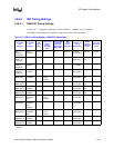
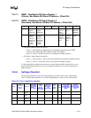
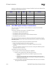
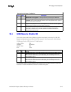
Register Type Offset Value Comments
PCI Command Register PCI 04h 0005h Ensure that bits 0 and 2 are ‘1’.
PCI Master Latency Timer PCI 0Dh system dependent
PCI Bus Master IDE Base I/O
Address
PCI 20-23h system dependent Ensure that bit 0
(of register value) is ‘1’.
IDE Timing Register 1 PCI 40-41h A307h mode config. for Primary
IDE Timing Register 2 PCI 42-43h A303h mode config. for Secondary
Secondary IDE Timing Register PCI 44h 00h
Ultra DMA Control Register PCI 48h 05h Drive 0 and 2 are Ultra DMA
capable.
Ultra DMA Timing Register PCI 4A-4Bh 0102h Ultra DMA mode config.


