


Intel® 460GX Chipset Software Developer’s Manual 11-27
LPC/FWH Interface Configuration
Register bit definitions are different during the Counter Latch Command than for a normal Timer
Counter Register write. Note that, If a counter is programmed to read/write two-byte counts, a
program must not transfer control between reading the first and second byte to another routine that
also reads from that same counter. Otherwise, an incorrect count will be read.
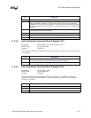
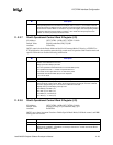
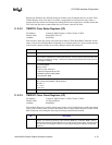
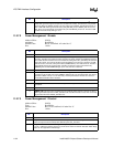
11.2.3.2 TMRSTS–Timer Status Registers (I/O)
I/O Address: Counter 0–040h; Counter 1–041h; Counter 2–042h
Default Value: Bits[6:0]=X; Bit 7=0
Attribute: Read Only
Each counter's status byte can be read following an Interval Timer Read Back Command. If latch
status is chosen (bit 4=0, Read Back Command) as a read back option for a given counter, the next
read from the counter's Counter Access Ports Register returns the status byte.
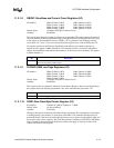
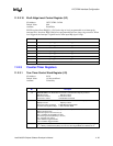
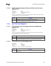
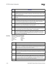
11.2.3.3 TMRCNT–Timer Count Registers (I/O)
I/O Address: Counter 0–040h; Counter 1–041h; Counter 2–042h
Default Value: All bits undefined
Attribute: Read/Write
Each of these I/O ports is used for writing count values to the Count Registers; reading the current
count value from the counter by either an I/O read, after a counter-latch command, or after a Read
Back Command; and reading the status byte following a Read Back Command.
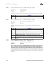
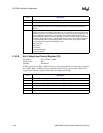
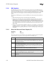
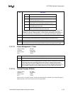
Bit Description
7 Counter OUT Pin State. 1=Pin is 1; 0=Pin is 0.
6 Count Register Status. This bit indicates when the last count written to the Count Register
(CR) has been loaded into the counting element (CE). 0=Count has been transferred from CR
to CE and is available for reading. 1=Count has not been transferred from CR to CE and is not
yet available for reading.
5:4 Read/Write Selection Status. Bits[5:4] reflect the read/write selection made through bits[5:4] of
the Control Register.
Bit[5:4] Function
00 Counter Latch Command
01 R/W Least Significant Byte (LSB)
10 R/W Most Significant Byte (MSB)
11 R/W LSB then MSB
3:1 Mode Selection Status. Bits[3:1] return the counter mode programming.
Bit[3:1] Mode Selected Bit[3:1] Mode Selected
000 0 X11 3
001 1 100 4
X10 2 101 5
0 Countdown Type Status. 0=Binary countdown; 1=Binary coded decimal (BCD) countdown.
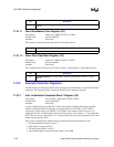
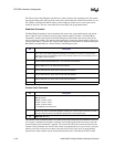
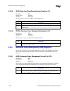
Bit Description
7:0 Counter Port Bits]. Each counter I/O port address is used to program the 16-bit Count
Register. The order of programming, either LSB only, MSB only, or LSB then MSB, is defined
with the Interval Counter Control Register. The counter I/O port is also used to read the current
count from the Count Register and return counter programming status following a Read Back
Command.