IDE Configuration
12-4 Intel® 460GX Chipset Software Developer’s Manual
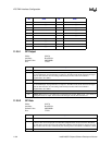
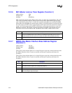
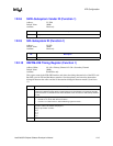
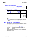
12.2.6 MLT–Master Latency Timer Register (Function 1)
Address Offset: 0Dh
Default Value: 00h
Attribute: Read/Write
MLT controls the amount of time IFB, as a bus master, can burst data on the PCI Bus. The count
value is an 8 bit quantity. However, MLT[3:0] are reserved and 0 when determining the count
value. The Master Latency Timer is cleared and suspended when IFB is not asserting FRAME#.
When IFB asserts FRAME#, the counter begins counting. If the IFB finishes its transaction before
the count expires, the MLT count is ignored. If the count expires before the transaction completes
(count = # of clocks programmed in MLT), IFB initiates a transaction termination as soon as its
PHLDA# is removed. The number of clocks programmed in the MLT represents the time slice
(measured in PCI clocks) allotted to IFB. The default value of MLT is 00h or 0 PCI clocks.
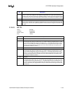
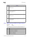
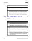
12.2.7 BMIBA–Bus Master Interface Base Address Register
(Function 1)
Address Offset: 20–23h
Default Value: 00000001h
Attribute: Read/Write
This register selects the base address of a 16 byte I/O space to provide a software interface to the
Bus Master Functions. Only 12 bytes are actually used (6 bytes for primary and 6 bytes for
secondary).
This register selects the base address of a 16 byte I/O space to provide a software interface to the
Bus Master Functions. Only 12 bytes are actually used (6 bytes for primary and 6 bytes for
secondary).
Bit Description
7:4 Master Latency Timer Count Value (MLTC). IFB-initiated PCI burst cycles can last indefinitely,
as long as PHLDA# remains active. However, if PHLDA# is negated after the burst cycle is
initiated, IFB limits the burst cycle to the number of PCI Bus clocks specified by this field.
3:0 Reserved.
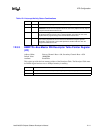
Bit Description
31:16 Reserved.
15:4 Bus Master Interface Base Address (BMIBA). These bits provide the base address for the
Bus Master interface registers and correspond to AD[15:4].
3:1 Reserved.
0 Resource Type Indicator (RTE)–RO. This bit is hardwired to 1 indicating that the base address
field in this register maps to I/O space.


