


Intel® 460GX Chipset Software Developer’s Manual 11-21
LPC/FWH Interface Configuration
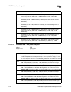
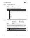
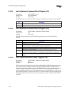
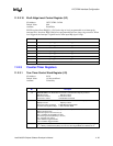
11.2.2.2 Icw2–Initialization Command Word 2 Register (I/O)
I/O Address: INT CNTRL-1–021h; INT CNTRL-2–0A1h
Default Value: All bits undefined
Attribute: Write Only
ICW2 is used to initialize the interrupt controller with the five most significant bits of the interrupt
vector address.
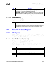
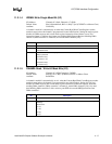
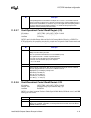
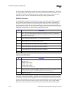
11.2.2.3 Icw3–Initialization Command Word 3 Register (I/O)
I/O Address: INT CNTRL-1–021h
Default Value: All bits undefined
Attribute: Write Only
The meaning of ICW3 differs between CNTRL-1 and CNTRL-2. On CNTRL-1, the master
controller, ICW3 indicates which CNTRL-1 IRQ line physically connects the INTR output of
CNTRL-2 to CNTRL-1.
Bit Description
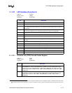
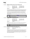
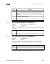
7:5 ICW/OCW select. These bits should be 000 when programming the IFB.
4 ICW/OCW select. Bit 4 must be a 1 to select ICW1. After the fixed initialization sequence to
ICW1, ICW2, ICW3, and ICW4, the controller base address is used to write to OCW2 and
OCW3. Bit 4 is a 0 on writes to these registers. A 1 on this bit at any time will force the interrupt
controller to interpret the write as an ICW1. The controller will then expect to see ICW2, ICW3,
and ICW4.
3 Edge/Level Bank Select (LTIM). This bit is disabled. Its Function is replaced by the Edge/
Level Triggered Control (ELCR) Registers.
2 ADI. Ignored for the IFB. This bit should be programmed to ‘0’.
1 Single or Cascade (SNGL). This bit must be programmed to a 0.
0 ICW4 Write Required (IC4). This bit must be set to a 1.
Bit Description
7:3 Interrupt Vector Base Address. Bits [7:3] define the base address in the interrupt vector table
for the interrupt routines associated with each interrupt request level input.
2:0 Interrupt Request Level. Must be programmed to all 0s.
Bit Description
7:3 Reserved. Must be programmed to all 0s.
2 Cascaded Mode Enable. This bit must be programmed to 1 selecting cascade mode.
1:0 Reserved. Must be programmed to all 0s.