IFB Power Management
16-2 Intel® 460GX Chipset Software Developer’s Manual
16.2 IFB Power Planes
16.2.1 Power Plane Descriptions
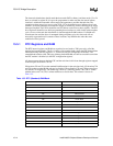
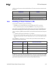
The IFB contains three power planes:
16.2.2 SMI# Generation
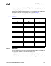
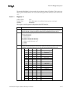
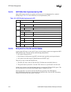
Table 16-2 shows which sources can cause the IFB to drive SMI# active. When operating with an
ACPI-based Operating System, some of the causes of SMI# will instead be routed to cause an SCI.
Upon any SMI# event taking place, the IFB will assert SMI#. SMI# remains active until the EOS
bit is set. When the EOS bit is set, SMI# will go inactive for a minimum of 1 PCICLK. If another
SMI event occurs, SMI# will be driven active again.
RTC Plane
This plane includes the RTC, as well as some of the power management
logic. It is intended to be backed up by a battery, even when all other
power to the system is shut.
Resume Plane
This plane contains additional power management logic, as well as other
circuits that can wake the systems from the S4-S5 states. The resume
plane will typically be powered by the main power supply’s trickle output.
Main (Core) Plane This includes all other signals.
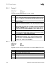
Table 16-2. Causes of SMI#
SMI Event Comment
ACPI SMI# bit (GBL_RLS) ACPI sets bit to cause SMI#, SMM handler clears the bit. ACPI I/O offset
04h, Bit 2
GPIO Assertion When a GPIO is programmed as an input and is set to a ‘1’, an SMI# will be
generated. The bit is cleared when the SMM handler clears the asserting
device.
Overflow of ACPI Timer Time-out every 2.34 seconds. If SCI_EN is set, the timer overflow will instead
cause an SCI.
THRM# signal The THRM# can cause an SMI# on either the rising or falling edge. If the
SCI_EN is set, the THRM# signal will instead cause an SCI.
Master Aborts of the IFB
DDMA Logic, USB Controller,
or IDE Controller
Internal bus master state machine sets bit. SMM handler will typically clear
the bit, then retry the cycle.
Legacy USB Support Bit set based on address decode or incoming USB IRQ. SMM handler will
clear bits.
1MIN Timer Needed for legacy power management, this time will generate an SMI# every
minute. The SMM handler can check the Wake/Break status register to see if
there is any system activity. After n minutes of no system activity (where n is
determine by the SMM handler), the SMM handler can decide to put the
system into a lower power state.
SW SMI# Timer Not to be confused with the above periodic SMI timer.


