LPC/FWH Interface Configuration
11-18 Intel® 460GX Chipset Software Developer’s Manual
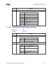
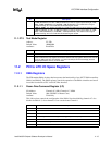
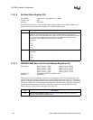
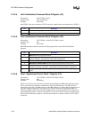
11.2.1.6 Ds–Dma Status Register (I/O)
I/O Address: Channels 0-3–08h; Channels 4-7–0D0h
Default Value: 00h
Attribute: Read Only
Each DMA controller has a read-only DMA Status Register that indicates which channels have
reached terminal count and which channels have a pending DMA request.
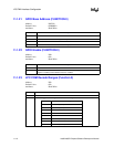
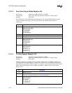
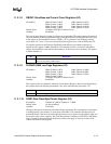
11.2.1.7 DBADDR–DMA Base and Current Address Registers (I/O)
I/O Address: DMA Channel 0–000h DMA Channel 4–0C0h
DMA Channel 1–002h DMA Channel 5–0C4h
DMA Channel 2–004h DMA Channel 6–0C8h
DMA Channel 3–006h DMA Channel 7–0CCh
Default Value: Undefined (CPURST or Master Clear)
Attribute: Read/Write
This Register works in conjunction with the Low Page Register. After an auto-initialization, this
register retains the original programmed value. Auto-initialize takes place after a TC. The address
register is automatically incremented or decrement after each transfer. This register is read/written
in successive 8-bit bytes. The programmer must issue the Clear Byte Pointer Flip-Flop command to
reset the internal byte pointer and correctly align the write prior to programming the Current
Address Register. Auto-initialize takes place only after a TC.
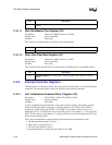
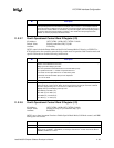
Bit Description
7:4 Channel Request Status. When a valid DMA request is pending for a channel (on its DREQ
signal line), the corresponding bit is set to 1. When a DMA request is not pending for a
particular channel, the corresponding bit is set to 0. The source of the DREQ may be hardware
or a software request. Note that channel 4 does not have DREQ or DACK lines, so the
response for a read of DMA2 status for channel 4 is irrelevant.
Bit Channel
4 0
5 1 (5)
6 2 (6)
7 3 (7)
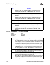
3:0 Channel Terminal Count Status. 1=TC is reached; 0=TC is not reached.
Bit Channel
0 0
1 1 (5)
2 2 (6)
3 3 (7)
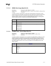
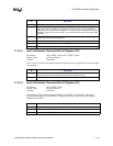
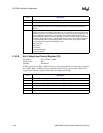
Bit Description
15:0 Base and Current Address [15:0]. These bits represent address bits [15:0] used when
forming the 24-bit address for DMA transfers.


