


Intel® 460GX Chipset Software Developer’s Manual 10-11
IFB Usage Considerations
10.5.6.2 Ultra DMA Timing Settings
The following settings apply to Ultra DMA Mode Settings only.
10.5.7 Drive Configuration for Selected Timings
Once the IFB Timing Modes for DMA, PIO and Ultra DMA have been selected, the Set Features
Command (0 x EF) with Set Transfer Mode (subcommand 0 x 03) can be issued to set the drives on
the system to the optimal speeds:
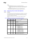
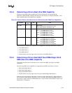
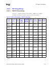
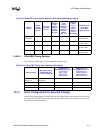
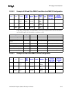
Table 10-9. DMA/PIO Timing Values Based on PIIX Cable Mode/System Speed
IFB Drive
Mode
IORDY
Sample
Point (ISP)
bits 1:0
Recovery
Time (RCT)
bits 1:0
IDETIMx
Value
Drive 0
(Master)
if Slave
Attached
bits 15:8
IDETIMx
Value
Drive 0
(Master) if
no Slave
Attached or
Slave is
Mode 0
bits 15:8
SIDETIM
Value
Drive 1
(Slave)
bits 3:0
(Primary) or
bits 7:4
(Secondary)
Resultant Cycle
Time (Total
Clocks Base
Operating Freq)
PIO0/
Compatible
Default Default C0h 80h 0 30 MHz: 900ns
33 MHz: 900ns
PIO2/SW2 4 clocks 4 clocks D0h 90h 4 30 MHz: 256ns
33 MHz: 240ns
PIO3/MW1 3 clocks 3 clocks E1h A1h 9 30 MHz: 198ns
33 MHz: 180ns
PIO4/MW2 3 clocks
1 clock E3h A3h B 30 MHz: 132ns
33 MHz: 120ns
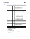
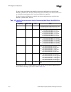
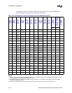
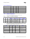
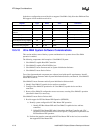
Table 10-10. Ultra DMA Timing Value Based on Drive Mode
IFB Drive Mode
DMA Speed Used on
DMA Based Data
Transfer Commands
SDMAC Value
Ultra DMA Mode Enable x:
Drive 0: bit 0
Drive 1: bit 1
Drive 2: bit 2
Drive 3: bit 3
SDMATIMx Value
Ultra DMA Cycle Time x:
Drive 0: bits 1:0
Drive 1: bits 5:4
Drive 2: bits 9:8
Drive 3: bits 13:12
N/A (Ultra DMA Not
Supported)
Non-ultra DMA
if supported
Disabled Default
Ultra DMA Mode 0 Ultra DMA Mode 0 Enabled 00b: CT=4 clks, RP=6 clks
Ultra DMA Mode 1 Ultra DMA Mode 1 Enabled 01b: CT=3 clks, RP=5 clks
Ultra DMA Mode 2 Ultra DMA Mode 2 Enabled 10b: CT=2 clks, RP=4 clks