


Universal Serial Bus (USB) Configuration
13-8 Intel® 460GX Chipset Software Developer’s Manual
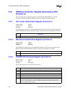
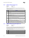
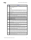
13.2.17 USBREN–USB Resume Enable
Address Offset: C4h
Default Value: 00h
Attribute: Read/Write
13.3 USB Host Controller I/O Space Registers
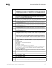
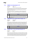
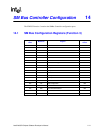
13.3.1 USBCMD–USB Command Register (I/O)
I/O Address: Base + (00-01h)
Default Value: 0000h
Attribute: Read/Write (WORD write-able only)
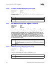
The Command Register indicates the command to be executed by the serial bus host controller.
Writing to the register causes a command to be executed. The table following the bit description
provides additional information on the operation of the Run/Stop and Debug bits.
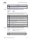
Bit Description
7:2 Reserved.
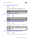
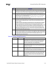
1 PORT1EN: Enable port 1 of the USB controller to look at wakeup events. When set, the USB
controller will monitor port 1 for a connect/disconnect, which is a resume event for USB. When
cleared, the USB controller will not look at this port for a wakeup event. This bit applies to port 1.
0 PORT0EN: Enable port 0 of the USB controller to look at wakeup events. When set, the USB
controller will monitor port 0 for a connect/disconnect, which is a resume event for USB. When
cleared, the USB controller will not look at this port for a wakeup event. This bit applies to port 0.
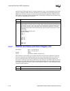
Bit Description
15:9 Reserved.
8 Loop Back Test Mode: When set, the IFB is in loop back test mode. When both ports are connected
together, a write to one port will be seen on the other port and the data will be store in I/O offset 18h.
When clear, this will not occur.
7 Max Packet (MAXP). 1=64 bytes. 0=32 bytes. This bit selects the maximum packet size that can be
used for full speed bandwidth reclamation at the end of a frame. This value is used by the Host
Controller to determine whether it should initiate another transaction based on the time remaining in
the SOF counter. Use of reclamation packets larger than the programmed size will cause a Babble
error if executed during the critical window at frame end. The Babble error results in the offending
endpoint being stalled. Software is responsible for ensuring that any packet which could be executed
under bandwidth reclamation be within this size limit.
6 Configure Flag (CF). HCD software sets this bit as the last action in its process of configuring the
Host Controller. This bit has no effect on the hardware. It is provided only as a semaphore service for
software.
5 Software Debug (SWDBG). 1=Debug mode. 0=Normal Mode. In SW Debug mode, the Host
Controller clears the Run/Stop bit after the completion of each USB transaction. The next transaction
is executed when software sets the Run/Stop bit back to 1. The SWDBG bit must only be
manipulated when the controller is in the stopped state. This can be determined by checking the
HCHalted bit in the USBSTS register.
4 Force Global Resume (FGR). 1=Host Controller sends the Global Resume signal on the USB.
Software sets this bit to 0 after 20 ms have elapsed to stop sending the Global Resume signal. At
that time all USB devices should be ready for bus activity. The Host Controller sets this bit to 1 when
a resume event (connect, disconnect, or K-state) is detected while in global suspend mode. Software
resets this bit to 0 to end Global Resume signaling. The 1 to 0 transition causes the port to send a
low speed EOP signal. This bit will remain a 1 until the EOP has completed.