


Register Descriptions
2-52 Intel® 460GX Chipset Software Developer’s Manual
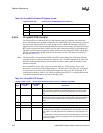
11 DESTINATION
MODE
DESTINATION
MODE
This bit determines the interpretation of the destination field.
A 0 indicates physical mode. In physical APIC mode, a destination APIC is
identified by its ID. Bits 56 through 59 of the destination field specify the 4-bit
APIC ID. In physical SAPIC mode, the destination ID is defined by bit 63
through 48 of the destination field.
A 1 indicates logical mode. In logical APIC mode, destinations are identified by
matching on logical destination under the control of the destination format
register and logical destination register in each local APIC. Bits 56 through 63
(8 MSB) of the destination field specify the 8-bit APIC ID. In logical SAPIC
mode, the destination field bits 63 through 56 make up 8 bits of the destination
ID. The remaining 8 bits are bits 55 through 48 of the destination field and must
always be programmed to 0.
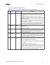
10:8 DELIVERY
MODE
DELIVERY
MODE
The delivery mode is a 3-bit field that specifies how the local (x)APIC units
listed in the destination field should act upon reception of this signal. Note that
certain delivery modes will only operate as intended when used in conjunction
with a specific trigger mode. These restrictions are indicated in the table below
for each delivery mode. Delivery mode encodings are shown below. Modes
001 and 010&Vector Field apply to APIC mode only:
00x (Fixed SAPIC Mode): This means deliver the interrupt on the INTR signal
of the processor listed in the destination. Trigger mode can be edge or level.
The least significant bit of this delivery mode is a HINT bit that is
communicated to the platform to allow it to redirect the interrupt to another
processor on the same processor system bus as the destination. The way this
redirection occurs is independent of platform implementation. Otherwise, the
processor can ignore the least significant bit.
000 (Fixed APIC Mode): This means deliver the signal on the INTR signal of
all processor cores listed in the destination field. Trigger mode for “fixed”
delivery mode can be edge or level.
001 (Lowest-Priority APIC Mode): This means deliver the interrupt on the
INTR signal of the processor core that is executing at the lowest-priority among
all the processors listed in the specified destination. Trigger mode for lowest-
priority delivery mode can be edge or level.
010 (PMI or SMI): Delivery mode is edge only. For systems that rely on SMI
semantics, the vector is ignored but must be all zeros for future upgrades. For
systems that rely on PMI semantics, the vector number has meaning and is not
ignored.
011 (Reserved).
100 (NMI): This means deliver the interrupt on the NMI signal of the processor
listed in the destination. Vector information is ignored. The NMI is always
delivered as an edge-triggered interrupt. The trigger mode field is ignored.
101 (INIT): This means deliver the interrupt on the INIT signal of the processor
listed in the destination. Vector information is ignored.
110 (Reserved).
111 (ExtINT): This means deliver the interrupt to the processor listed in the
destination as an interrupt that originated in an externally connected (8259A-
compatible) interrupt controller. The INTA cycle that corresponds to this ExtINT
delivery will be routed to the external controller that is expected to supply the
vector. A delivery mode of ExtINT requires an edge-triggered mode. ExtINT
should be targeted for only one processor.
7:0 VECTOR VECTOR This is the vector number identifying the interrupt being sent.
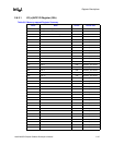
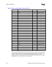
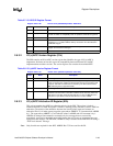
Table 2-10. I/O (x)APIC RTE Format (Cont’d)
Register Offset: 10-8Fh Default Value: Undefined except mask bit is 1Attribute: Read/Write
Bit(s)
SAPIC Mode
Name
APIC Mode
Name
Description