


Intel® 460GX Chipset Software Developer’s Manual 11-33
LPC/FWH Interface Configuration
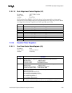
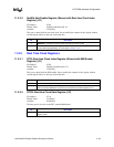
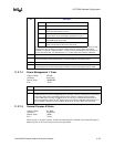
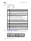
11.2.7.4 Power Management 1 Timer
Address Offset: 08-0Bh
Attributes: Read Only
Default Value: 00000000h
Size: 32 bits
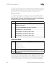
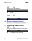
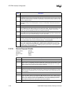
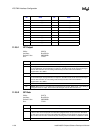
11.2.7.5 General Purpose 0 Status
Address Offset: 0C-0Dh
Attributes: Read/Write
Default Value: 0800h
Size: 16 bits
When any bit is set in this register, and the corresponding bit is enabled in the General Purpose 0
Enable register, an SCI and a wake event will be generated.
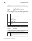
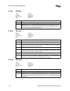
Bits Mode
000 ON
001 Typically mapped to S1 state. STPCLK# active. CPU in Stop-
Grant state. Equivalent to Level 2.
010 Typically mapped to S1 state. Both STPCLK# and SLP#
signals active. CPU in Sleep state. Equivalent to Level 3.
011 S3 state. This is also known as Suspend-To-RAM (STR).
The SUSB signal will go active.
100 S4/S5 state. The S4 state is also known as Suspend-To-Disk
(STD). The S5 state is also known as Soft-Off.
All other combinations are reserved. If a value is written other than those shown above, the IFB
will ignore the value and stay in the ON (000) state. However, the last written value will be
readable. For example, if software writes 111 (reserved value), IFB will stay in the ON state, but
the next read to the SLP_TYP field will return 111, not 000. Upon reset, this bit is undefined.
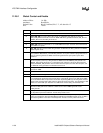
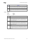
9:3 Reserved.
2 GBL_RLS: This bit is used by the ACPI software to generate an SMI to the firmware. Firmware
has corresponding enable and status bits to control its ability to receive ACPI events.
1 Reserved.
0 SCI_EN: Selects the SCI interrupt for the THRM_STS and Timer. When this bit is 1, then these
events will generate an SCI interrupt. When this bit is 0, these events will generate an SMI#.
Bit Description
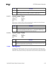
Bit Description
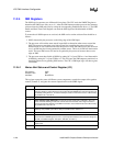
31:24 Reserved.
23:0 TMR_VAL: This read-only field returns the running count of the power management timer. This is a
24-bit counter that runs off a 3.579545 MHz clock. The timer is reset to an initial value of zero during
a PCI reset, starts running immediately after PCI reset, and then continues counting until the
14.31818 MHz input to the chip is stopped (which can only occur in STR/STD and the power is
removed to the IFB). Anytime the 22
nd
bit of the timer goes HIGH to LOW (bits referenced from 0 to
23), the TMROF_STS bit is set. If the TMROF_EN bit is set, an SCI or SMI is also generated.