Intel® 460GX Chipset Software Developer’s Manual 11-7
LPC/FWH Interface Configuration
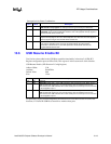
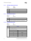
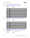
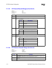
11.1.15 MSTAT–Miscellaneous Status Register (Function 0)
Address Offset: 6A–6Bh
Default Value: 0000h
Attribute: Read/Write
This register provides miscellaneous status and control Functions.
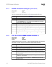
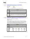
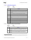
11.1.16 Deterministic Latency Control Register (Function 0)
Address Offset: 82h
Default Value: 00h
Attribute: Read/Write
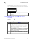
This register enables and disables the Delayed Transaction and Passive Release Functions. When
enabled, these Functions make the IFB PCI revision 2.1 compliant.
The PCI specification requires much tighter controls on target and master latency. Targets must
respond with TRDY# or STOP# within 16 clocks of FRAME#, and masters must assert IRDY#
within 8 PCI clocks for any data phase. PCI cycles to or from LPC typically take longer than this.
The IFB provides a programmable delayed completion mechanism described in the PCI
specification to meet the required target latencies.
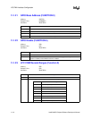
Bit Description
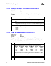
15 SERR# Generation Due To Delayed Transaction Time-out–R/WC. This status bit is set
whenever the IFB times out a cycle it was running as a delayed transaction, bit 3 (Delayed
Transaction SERR# enable) of offset 82h is set, and bit 8 (SERR# enable) of offset 4h is set.
When a master does not return for the data within 1 ms of the cycle’s completion, the IFB
asserts SERR#, clears the delayed transaction, and sets this bit. If either bit 3 of 82h or bit 8
of 4h is not set then this bit will not get set and SERR# will not be generated. The IFB will still
discard the delayed transaction cycle. The bit can be cleared by writing “1” to it via software.
14:1 Reserved.
0 ECC SERR# Enable: When this bit is a “1”, it enables a one clock pulse on ECCINT# to
instead be routed to generate SERR#. This allows ECC scrubbing through SMI (greater than
one clock) or NMI (one clock).
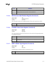
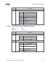
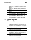
Bit Description
7:4 Reserved.
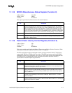
3 SERR# Generation Due To Delayed Transaction Time-out Enable. When this bit is set,
and bit 8 (SERR# enable) of the Command Register (offset 4h) is set, the IFB will generate
SERR# when a delayed transaction cycle times out.
2 USB Passive Release Enable (USBPR). When this bit is set, the IFB enables the passive
release mechanism for USB. Normally, if the IFB gets retried under USB, it will not remove
PHOLD#. This bit is needed due to posting of USWC cycles, which means a retry might be
due to a USWC flush.
1 Passive Release Enable. When this bit is a “1”, it enables the Passive Release mechanism
encoded on the PHOLD# signal when IFB is a PCI Master. When this bit is a “0”, Passive
Release is disabled.
0 Delayed Transaction Enable. When this bit is a “1”, it enables the Delayed Transaction
mechanism when the IFB is the target of a PCI transaction. When this bit is a “0”, the Delayed
Transaction mechanism is disabled.


