


Intel® 460GX Chipset Software Developer’s Manual 15-13
PCI/LPC Bridge Description
If a counter is programmed to read/write two-byte counts, a program must not transfer control
between reading the first and second byte to another routine which also reads from that same
counter. Otherwise, an incorrect count will be read.
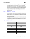
15.4.1.6 Read Back Command
The third method uses the Read Back Command. The Read Back Command is used to determine
the count value, programmed mode, and current states of the OUT pin and Null Count flag of the
selected counter or counters. The Read Back Command is written to the Control Word Register,
which causes the current states of the above mentioned variables to be latched. The value of the
counter and its status may then be read by I/O access to the counter address.
The Read Back Command may be used to latch multiple counter output latches (OL) by setting the
COUNT# bit D5=0 and selecting the desired counter(s). This single command is Functionally
equivalent to several counter latch commands, one for each counter latched. Each counter’s latched
count is held until it is read (or the counter is reprogrammed). Once read, a counter is automatically
unlatched. The other counters remain latched until they are read. If multiple count Read-Back
Commands are issued to the same counter without reading the count, all but the first are ignored
(i.e. the count which will be read is the count at the time the first Read-Back Command was
issued).
The Read Back Command may also be used to latch status information of selected counter(s) by
setting STATUS# bit D4=0. Status must be latched to be read. The status of a counter is accessed
by a read from that counter’s I/O port address.
If multiple counter status latch operations are performed without reading the status, all but the first
are ignored. The status returned from the read is the counter status at the time the first status Read
Back Command was issued.
Both count and status of the selected counter(s) may be latched simultaneously by setting both the
COUNT# and STATUS# bits [5:4]=00. This is functionally the same as issuing two consecutive,
separate Read Back Commands. The above discussions apply here also. Specifically, if multiple
count and/or status Read Back Commands are issued to the same counter(s) without any
intervening reads, all but the first are ignored.
If both count and status of a counter are latched, the first read operation from that counter will
return the latched status, regardless of which was latched first. The next one or two reads
(depending on whether the counter is programmed for one or two type counts) return the latched
count. Subsequent reads return unlatched count.
15.5 Real Time Clock
The Real Time Clock (RTC) module provides a battery backed-up date and time keeping device
with two banks of static RAM with 128 bytes each, although the first bank has 114 bytes for
general purpose usage. Three interrupt features are available: time of day alarm with once a second
to once a month range, periodic rates of 122 µs to 500 ms, and end of update cycle notification.
Seconds, minutes, hours, days, day of week, month, and year are counted. Daylight savings
compensation is optional. The hour is represented in twelve or twenty-four hour format, and data
can be represented in BCD or binary format. The time keeping comes from a 32.768 kHz
oscillating source, which is divided to achieve an update every second. The lower 14 bytes on the
lower RAM block have very specific Functions. The first ten are for time and date information.
The next four (0Ah to 0Dh) are registers, which configure and report RTC Functions.