


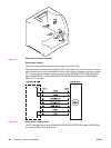
Engine control system
The engine control system functions as the brain of the printer. It controls the laser/scanner
system, the image formation system, and the pickup/feed system according to the
commands received from the formatter.
The engine control system consists of the following:
● DC controller printed circuit board (PCB) assembly
● High-voltage power supply PCB
● Low-voltage power supply PCB
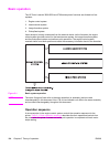
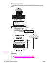
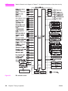
The block diagram below illustrates the engine control system. Each circuit is described in
the following paragraphs.
Figure 5-4.
Engine control system
NOTE
Components described as a PCB may consist of a single circuit board or a circuit board plus
other parts, such as cables and sensors.
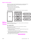
DC controller PCB
The DC controller PCB is controlled by the CPU on the DC controller. It controls the
operation sequences of this printer.
The following is the sequence of the DC controller PCB:
1. The power switch is turned on, the DC controller is supplied with the DC power from the
low-voltage power supply unit.
2. The CPU starts to control the operations of the printer.
3. When the printer enters the STBY period, the CPU sends signals to drive each load
(such as the laser diode, the motors, and the solenoids) based on the print command
and the image data received from the formatter.
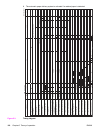
The block diagram of this circuit is illustrated in
Figure 5-5. DC controller circuit.
ENWW Engine control system 119