


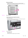

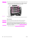
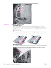
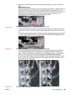
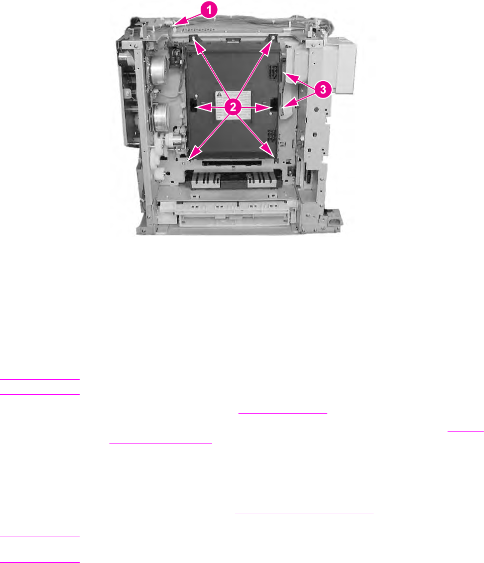
4. Remove six screws (2) and pull the laser/scanner assembly out slightly, disconnect two
flat cables (3), and remove the assembly.
Figure 6-22.
Laser/scanner assembly removal
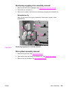
Reinstallation tip
Connect the connectors (see callout (3) above) first, then install the laser/scanner
assembly. Ensure that the top of the laser/scanner fits into the slots first before installing
the remainder of the unit.
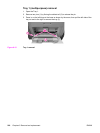
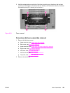
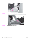
Image drive assembly removal
CAUTION
Do not disassemble the image drive assembly.
1. Remove the right cover. See
Right cover removal.
2. Push the engaging rack (1) all the way back to the right until it stops. Refer to
Pick-up/
feed assembly removal procedure, step 7, for additional information.
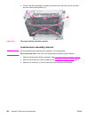
Reinstallation tip
Once the image drive assembly has been reinstalled, the engaging rack (1) must be
pushed to the left, forward towards the front of the printer as far as it will go to return it to
its original position. Refer to
Pick-up/feed assembly removal, step 8 "Reinstallation Tip"
for additional information on positioning the engaging rack.
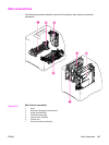
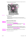
CAUTION
Incorrect installation can result in damage to the print cartridge drive pins, the image drive
assembly drive pins, and the swing guide mechanism.
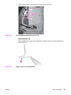
3. Disconnect one connector (2).
ENWW Main Assemblies 223