


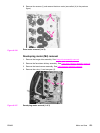
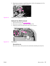
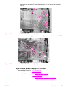
d. Disconnect one connector (1), remove two screws (2), and remove the formatter
cover (3).
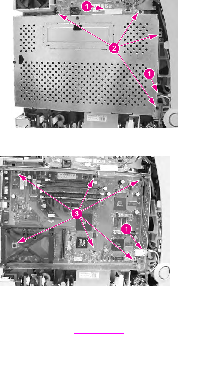
Figure 6-119.
Formatter PCB (HP 3700) removal (1 of 2)
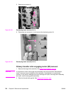
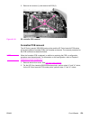
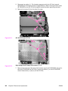
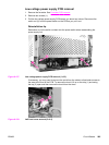
3. Disconnect one connector (1), remove six screws (2), and remove the formatter PCB (3).
Figure 6-120.
Formatter PCB (HP 3700) removal (2 of 2)
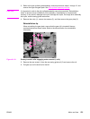
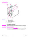
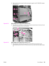
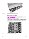
High-voltage power supply PCB removal
1. Remove the top cover. See Top cover removal.
2. Remove the upper rear door. See
Upper rear door removal.
3. Remove the rear cover. See
Rear cover removal.
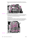
4. Remove the lower rear door. See
Lower rear door (rear output bin) removal.
ENWW Circuit Boards 281