


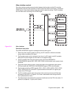
Video interface control
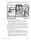
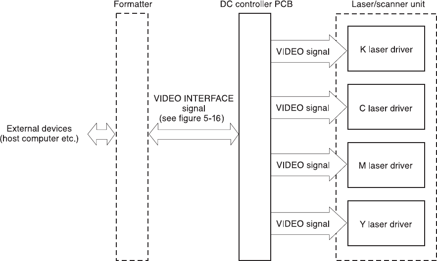
The video interface enables communication between the formatter and the DC controller.
The formatter uses the video interface to monitor the printer status continuously. It sends the
VIDEO signal via the video interface when the printer is ready for printing. The DC controller
turns the laser on/off according to the VIDEO signal.
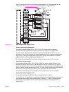
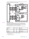
Figure 5-16.
Video interface
Operational description
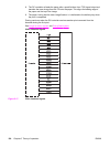
The VIDEO INTERFACE signal is exchanged as follows during print:
1. When the printer engine is ready for printing, the DC controller notifies the formatter
using a status command (SC) signal.
2. The formatter sends a print command in the form of an SC signal to the DC controller
when both the printer engine and the data for one page are ready.
3. The DC controller that drives the scanner motor sends the HORIZONTAL
SYNCHRONOUS signals (/BD1, /BD2, /BD3, /BD4) to the formatter upon receipt of print
command.
4. The printer engine picks up paper. It stops the paper at the registration paper sensor
(PS4) and sends the VERTICAL SYNCHRONOUS signal (/TOP) to the formatter.
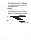
5. The formatter sends the VIDEO signals (VDO1, /VDO1, VDO2, /VDO2, VDO3, /VDO3,
VDO4, /VDO4) to the DC controller in synchronization with the /BD1~4 signals upon
receipt of the /TOP signal.
6. The DC controller controls each color’s laser driver circuits and turns on/off the laser
according to the VDO11~41 signals. This forms a electrostatic latent image on each
color’s photosensitive drums.
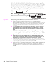
7. The latent images are developed by toner and transferred onto the ITB in the order of Y
(yellow), M (magenta), C (cyan), and K (black).
ENWW Engine control system 135