


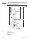
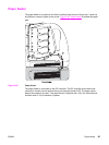
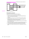

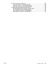
Figure 5-66. Paper feeder PCB signal flow illustrates the flow of signals to and from the
paper feeder PCB.
Figure 5-66.
Paper feeder PCB signal flow
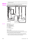
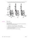
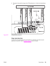
Pickup/delivery sequence
The paper feeder is driven by the feed motor (M1) via a gear.
The following is the sequence of paper pickup at the paper feeder.
1. The printer controls the fuser heater temperature and drives the scanner motor upon
receipt of a print command from the formatter.
2. The feed motor (M1) drives when the fuser heater temperature reaches the specified
temperature.
3. After the specified period after the scanner motor drive has started, the paper feeder
pickup solenoid (SL3) is turned on. The pickup roller rotates and picks paper up. The
double feeding of paper is prevented by the separation pad.
As the paper feeder pickup clutch (CL4) is engaged, the feed roller rotates and feeds the
paper to the registration roller.
4. When the paper is detected by the registration paper sensor (PS4) after passing through
the roller, the paper feeder pickup clutch (CL4) is disengaged and the paper stops.
5. At the specific timing when the leading edge of paper should match the edge of the
image on the ITB, the paper feeder pickup clutch (CL4) is engaged again to re-feed the
paper.
198 Chapter 5 Theory of operation ENWW