


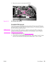
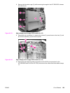
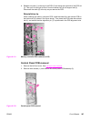
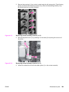

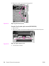
4. Release one claw (1) at the top of the PCB (2) and swing the right side of the PCB out
(3). Then pull it to the right to free it from the retainer tab (4) and support tab (5).
Disconnect the cable (6) at the top as you remove the PCB.
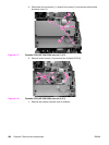
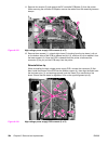
Reinstallation tip
When installing the memory controller PCB, install the cable first, then set the PCB on
the bottom tab (5) (shown in the figure above). Then insert the PCB under the retainer
tab (4), and ensure that the alignment pin (7) is positioned in the PCB alignment hole.
7
Figure 6-131.
Memory controller PCB removal (2 of 2)
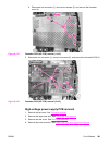
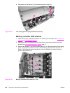
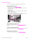
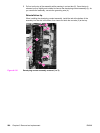
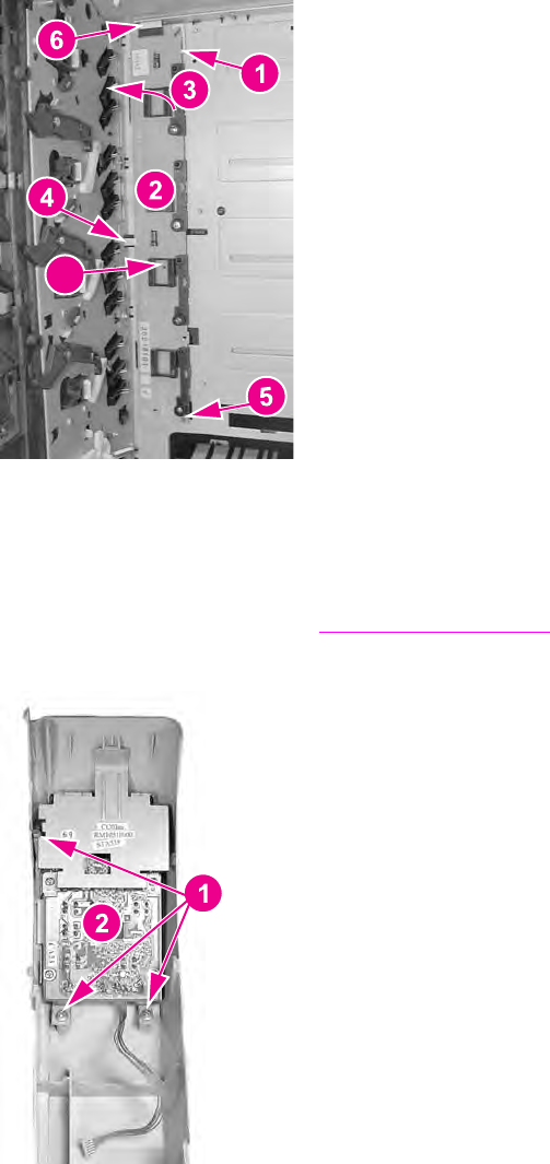
Control Panel PCB removal
1. Remove the left front cover. See Left front cover removal.
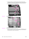
2. Remove three screws (1) and remove the control panel PCB assembly (2).
Figure 6-132.
Control panel PCB removal
ENWW Circuit Boards 287