


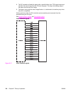

Failure detection
This control monitors any failure of the laser diode.
The laser IC converts the laser current of the LD to voltage during initial APC and sends the
PDOUT signal to the CPU. When the voltage of the PDOUT signal is below a specified
value, the CPU judges the laser faulty and informs the formatter.
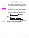
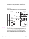
Scanner motor control
This control rotates the scanner motor to strike the laser beam at the correct position on the
photosensitive drum.
The scanner motor, which is integral with this drive circuit, is a three-phase, eight-pole DC
brushless motor with a built-in Hall device.
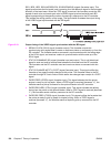
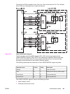
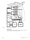
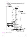
Figure 5-23.
Scanner motor control
The DC controller performs this control. The DC controller generates the reference clock
based on the oscillation frequency of the oscillator (X1001). It compares the intervals
between the reference clock and the BD INPUT signal (/BD2I) in the frequency comparator
and monitors the RPM of the scanner motor. The DC controller sends the SCANNER
MOTOR ACCELERATION signal (/ACC1) or the SCANNER MOTOR DECELERATION
signal (/DEC1) to the scanner motor driver according to the monitored speed to control the
rotation speed of the motor.
The following sections describe each control performed by the scanner motor control.
144 Chapter 5 Theory of operation ENWW