


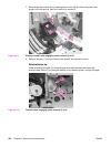
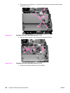
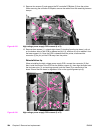
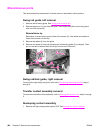
11. Remove four screws (2) and remove the DC controller PCB/plate (3) from the printer.
While removing the controller PCB/plate, remove the cables from the remaining harness
clamps.
Figure 6-125.
High-voltage power supply PCB removal (4 of 5)
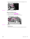
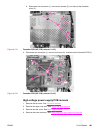
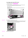
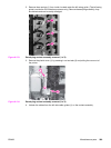
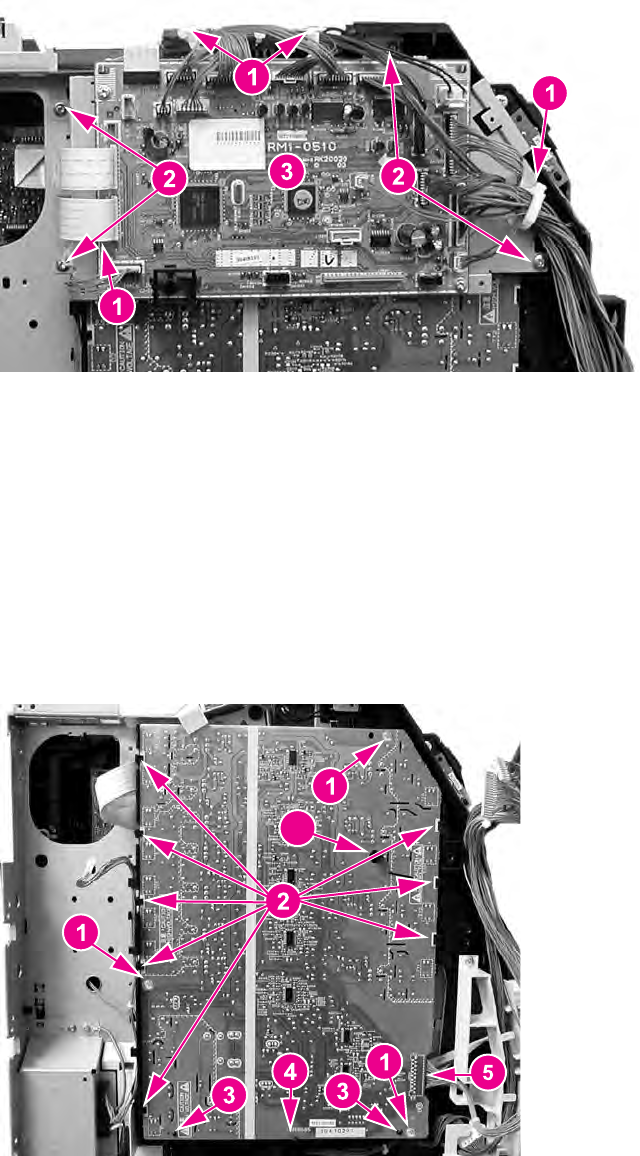
12. Remove three screws (1), unhook eight claws (2) (working from the top down), pull out
on the bottom sides of the PCB to release two pins (3), and then lift up to release it from
the lower support (4). Once the PCB is released from the printer, disconnect the
connector (5) as you pull the PCB away from the printer.
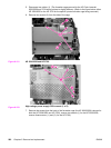
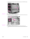
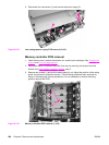
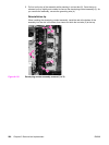
Reinstallation tip
When reinstalling the high-voltage power supply PCB, connect the connector (5) first.
Next, install the bottom of the PCB into the bottom support (4), then align the board onto
the two lower pins (3), and working upward, hook the claws (2) on each side of the
board. Ensure that the board is aligned so it fits on the upper alignment pin (6).
6
Figure 6-126.
High-voltage power supply PCB removal (5 of 5)
284 Chapter 6 Removal and replacement ENWW