


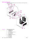

Main assembly parts
The following procedures describe removal of parts located on or around the major internal
mechanical assemblies.
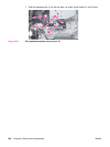
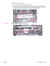
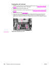
Figure 6-43.
Main assemblies parts location
1 Sub thermistor (TH2)
2 Main thermistor (TH1)
3 Thermoswitch (TP)
4 Fuser sleeve unit
5 Tray 1 (multipurpose) pick-up roller
6 Tray 1 separation pad
7 Tray 2 pick-up roller
8 Tray 2 separation pad
9 Secondary transfer charging roller
10 Pressure roller
11 Left swing guide
12 Right swing guide
13 Tray 1 guide unit
14 Feed guide unit
236 Chapter 6 Removal and replacement ENWW