


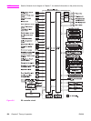

The heater temperature control controls the drive signals of the fuser heater to monitor and
maintain the surface temperatures of the fuser sleeve and the fuser heater at the target
temperature.
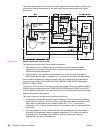
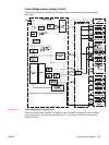
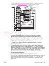
Figure 5-13.
Heater temperature control circuit
Two thermistors monitor fuser (fixing) heater temperature:
● Main thermistor (TH1): Monitors the print temperature and the between-sheets
temperature. It is placed in contact with the inside surface of the fuser sleeve and
monitors the sleeve temperature.
● Sub thermistor (TH2): Monitors the temperature rise at the end, the initial rotation
temperature, and the start-up temperature. It is placed in contact with the fuser heater.
As the surface temperature of the fuser heater rises, the resistances of both thermistors
reduce and the voltage of the FUSER HEATER TEMPERATURE DETECTION signals
(MAINTH, SUBTH) varies.
The CPU (IC1001) on the DC controller monitors the voltage of these two signals (MAINTH,
SUBTH) and accordingly sends the FUSER HEATER DRIVE signal (FSRD) via the ASIC
(C1002). Based on this signal, the fuser heater drive circuit controls and maintains the fuser
heater at the specified temperature.
This control system is divided into the following five controls.
● Initial rotation temperature control: Prevents damage to the fuser sleeve unit when the
power switch is turned on. The CPU turns on the fuser heater before it drives the feed
motor when the temperature of the heater is below 55˚ C (131˚ F) on switch-on
(detected by TH2). It drives the motor after the fuser heater is left on for the prescribed
time period.
● Start-up temperature control: Determines the initial temperature of the fuser heater
according to its temperature when energized (detected by TH2). When the heater is
energized within 30 seconds after completion of a print, the previous printing
temperature is the start-up temperature.
128 Chapter 5 Theory of operation ENWW