


● Horizontal synchronization control
● Image masking control
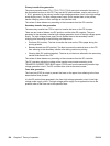
The LASER CURRENT OUTPUT signal (PDOUT) is an analog signal generated by
transforming the amount of laser to a current value. The DC controller obtains each laser’s
light amount based on the PDOUT signal and passes such information on to the formatter,
while the formatter adjusts the PWM (adjusts the laser emission timing according to the
halftone).
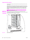
Laser emission control
The laser emission control controls on/off of the laser diode (LD) according to the VIDEO
signals. When the DC controller puts the laser driver circuit into print mode, the laser driver
circuit turns on/off the LD at a specified light amount according to the VIDEO signals (VDO, /
VDO) received from the formatter.
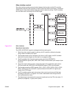
Automatic photocurrent control (APC)
This control ensures that the amount of light emitted by the LD remains constant. There are
two APCs, both of which are controlled by the laser driver circuit in the same way.
● Initial APC: Performed at the scanner motor startup; adjusts the amount of laser light.
● Between-lines APC: Performed during the print process; adjusts the amount of laser
light for the next one line before it is written.
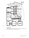
The following is the sequence of APC control.
1. When the DC controller puts it into Force LD ON mode, the laser driver circuit forces the
LD to emit light.
2. The light amount of the LD is detected by the photo diode (PD) and is converted to
voltage level. Then it is compared with the reference voltage (voltage equivalent to the
target laser light amount) inside the laser driver IC.
3. The laser driver circuit controls the laser current until the voltage level of the laser light
amount reaches the reference voltage.
4. The laser driver circuit is put to Force LD OFF mode to turn the LD OFF and it stores the
adjusted laser light amount in the capacitors (IC103, IC112).
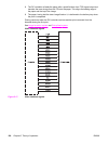
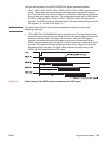
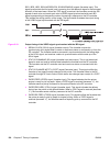
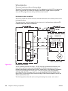
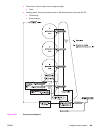
Horizontal synchronous control
The horizontal synchronous control horizontally aligns the scanning starting position of the
image. This control performs the following steps.
1. The DC controller puts the laser driver circuit into Force LD ON mode during the
unblanking interval to force the LD to emit light. (The unblanking interval is the interval
when a LD emits light in the non-image area.)
2. The laser beam is reflected from the BD mirror, fixed at the scanning starting position in
the optical path of the laser beam, and sent to the BD circuit in the laser/scanner unit.
3. The BD circuit detects the laser beam, generates a BD INPUT signal (/BD2I), and sends
the signal to the DC controller.
4. The DC controller generates the HORIZONTAL SYNCHRONOUS signal (Y:/BD1, M:/
BD2) based on the /BD2I signal and sends it to the formatter. (The signal /BD21 is
generated fresh based on the signal BD1, although both signals are output at the same
time.)
142 Chapter 5 Theory of operation ENWW