


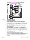
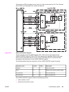
The types and purposes of the VIDEO INTERFACE signals are described below.
● VDO1, /VDO1, VDO2, /VDO2, VDO3, /VDO3, VDO4, /VDO4, (VIDEO) signals (formatter
output): These signals are the information of the image the printer engine is going to
print. The laser drivers turn the laser diode on or off based on these signals. This printer
has four laser units, one for each color. The formatter sends each color’s VIDEO signal
(Y=VDO1, /VDO1 M=VDO2, /VDO2 C=VDO3, /VDO3 Bk=VDO4, /VDO4) to the DC
controller. The VIDEO signal is a differential signal. The laser diode emits light when the
VDO signal is “H”, and the /VDO signal is “L”.
NOTE
The abbreviations Bk and K are used interchangeably and refer to the black toner
developing operations.
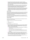
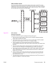
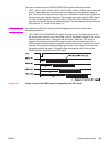
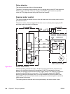
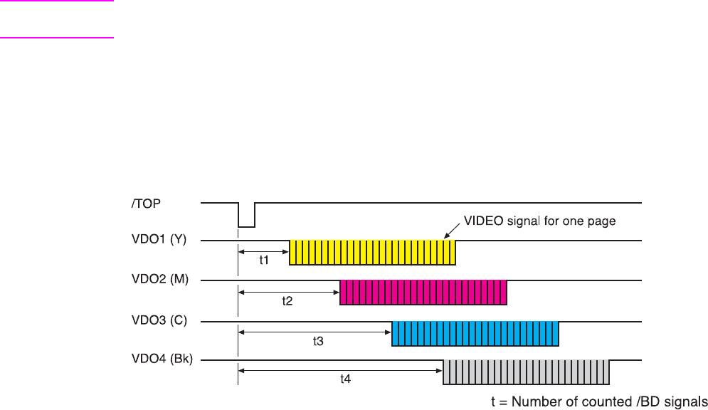
● /TOP (VERTICAL SYNCHRONOUS) signal (formatter input): This signal synchronizes
the vertical (sub) scanning line of the image, which is the reference signal in the vertical
direction of the laser beam. This printer has four drums. When the /TOP signal is
received, the formatter counts the /BD signals of each color and sends each color’s
VIDEO signals corresponding to the specific number of scanning in sequence to the DC
controller. This synchronizes the leading edge of each color’s image on the drum with
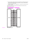
the leading edge of the paper. The figure below illustrates the output timing of the
VIDEO signals in response to the /TOP signal.
Figure 5-18.
Output timing of the VIDEO signal in response to the /TOP signal
ENWW Engine control system 137