


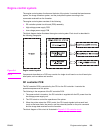
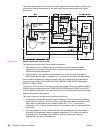
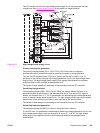
Fuser control circuit
The fuser control circuit controls the temperature of the fuser. The following figure shows the
ceramic heater fusing method used by this printer.
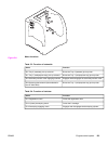
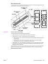
Figure 5-12.
Ceramic heater fusing method
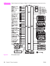
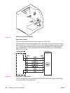
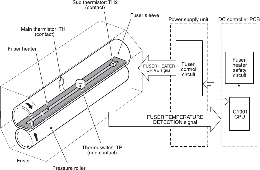
The fuser control circuit has three main components:
● Fuser heater (H1): A ceramic heater that heats the fuser sleeve.
● Thermistors (TH1, TH2): Two thermistors monitor temperature:
● Main thermistor (TH1): Monitors print temperature and between-sheets temperature
(contact type).
● Sub thermistor (TH2): Monitors temperature rise at the end, the initial rotation
temperature, and the start-up temperature (contact type).
● Thermoswitch (TP): One thermoswitch is placed on top of the fuser heater (non-contact
type). When the fuser heater is abnormally overheated, the switch opens and cuts off
the power supply to the heater.
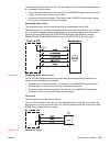
The temperatures in the fuser are controlled by the fuser control circuit and the fuser heater
safety circuit according to the commands from the CPU (IC1001) on the DC controller.
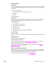
Heater temperature control
ENWW Engine control system 127